Chapter 3 Installation and Wiring 17
4. Motor cables should be as short as possible so as to reduce the leakage
current to earth.
5. Selection of control cables
Generally, the control cables should be shielded and the shield must be
connected to the metal enclosure of the drive by cable clamps at both ends.
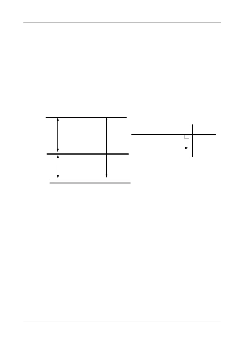
6. Control cables, input power cables and motor cables should be installed
separately
Adequate clearance should be left between the cables, especially when the
cables are laid in parallel and long. If the signal cables have to cross over the
power cables, keep them vertical to each other, as shown in Figure 3-8.
Power source
or motor cable
Motor cable
Signal/Control
cable
Power cable
>50cm
>30cm
>20cm
Signal/Control
cable
Figure 3-8 Wiring requirements
7. Installation requirements of relay, contactor and electro-magnetic braking
kit, which may generate great noises, should be installed outside of the drive
cabinet and installed with surge suppressors.
The suppressors are generally varistor, RC filter or diode as illustrated in
Figure 3-9:
TD3200 Variable Speed Drive for Elevator Door Control User Manual
 Loading...