Safety
Information
Introduction Installation
PowerTools
Pro Software
Communications
How
Motion
Works
How I/O
Works
Configuring
an
Application
Programming
Starting and
Stopping
Motion
Starting and
Stopping
Programs
Parameter
Descriptions
Drive
Parameters
Used by
EZMotion
Diagnostics Glossary Index
EZMotion User/Programming Guide 133
Revision A8 www.controltechniques.com
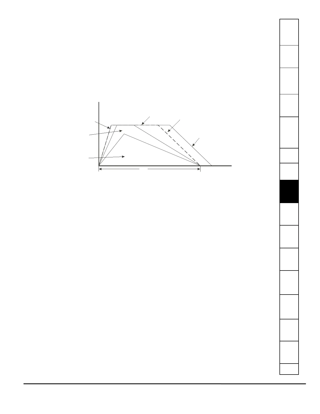
this situation, the index will still operate, but the time will be extended. In other words, the profile will be performed using the
maximums values and still cover the specified distance, but not in the specified time.
The units for the Time parameter depend on the current setting of the Time Base parameter.
If Time Base is set to "Realtime" (default), then the units for the Time parameter are Seconds. The user can program the index
time with resolution of 0.001 Seconds (or milliseconds). If Time Base is set to "Synchronized", the units for the Time parameter
are defined by the Master Distance Units found on the Master Setup screen.
Doing a synchronized Timed Index means that the user can specify the master distance in which the index should be
performed. This can be very useful in many synchronized motion applications.
The internal calculations are designed to calculate a triangular profile (all accel and decel). The ratio of acceleration to
deceleration will be the same ratio as Max. Acceleration to Max. Deceleration parameters. For example, if the deceleration is
desired to be twice the acceleration, a number twice the value of max acceleration would be entered for maximum
deceleration. Even in trapezoidal moves, the same ratio of acceleration and deceleration is maintained.
The calculations are based on the assumption that Feedrate Override is set to 100%. If set to greater that 100%, the motor
could run in excess of the specified Max. Velocity.
Figure 142: Timed Index Profile Diagram
Enable Index PLS Check Box
This check box enables (when selected) or disables (when clear) the Index PLS function.
An Index PLS is similar to a global PLS (explained in the PLS View section), but is incremental in nature. The Index PLS has
On and Off points just like a global PLS, but the On and Off points are specified as an incremental distance from the start of
the index, instead of absolute positions. Each index has its own On and Off points, and the Index.#.PLSStatus is only updated
when Index# is run. The direction of the PLS does not matter, the Index.#.PLSStatus will activate and deactivate the same
incremental distance from the start of the index.
PLS On Point
This parameter is an incremental distance from the start position of the index, at which the PLS.#.Status will become active. It
is an unsigned value in user units. The On Point must always be less than the Off Point.
PLS Off Point
This parameter is an incremental distance from the start position of the index, at which the PLS.#.Status will deactivate. It is an
unsigned value in user units. The Off Point must always be greater than the On Point. If the Off Point is larger than the
Distance parameter in an Incremental type of index, the PLS Status will never deactivate until the index is run again.
Examples:
Example 1:
Index 0 is an Incremental index with a distance of 5 Revs. The PLS On Point is set to 1 Rev, and the PLS Off Point is set to 4
Revs. A home is completed, and Position Feedback is equal to 0.0 Revs.
If Index 0 is run, the Index.0.PLSStatus will activate when the feedback position reaches 1 Rev and remain active until
feedback position reaches 4 Revs, and deactivate. At the end of Index 0, position feedback is equal to 5 Revs. If we initiate
Index 0 again, Index.0.PLSStatus will activate 1 Rev into the index, or at 6 Revs. It will remain active until position feedback
reaches 9 Revs, and deactivate. This index could be run over and over again, and Index.0.PLSStatus will activate 1 Rev from
the starting position and deactivate 4 Revs from the starting position every time.
Example 2:
Index 1 is an Incremental index with a distance of -10 revs. The PLS On Point is set to 4 Revs, and the PLS Off Point is set to
6 Revs. A home is completed, and Position Feedback is equal to 0.0 Revs.
If Index 1 is run, the Index.1.PLSStatus will activate when the position feedback reaches -4 Revs (or 4 Revs from the start of
the index). Index.1.PLSStatus will then deactivate when position feedback reaches -6 Revs (or 6 Revs from the start of the
index). If Index 1 is run again, Index.1.PLSStatus will activate and deactivate at -14 Revs and -16 Revs respectively.
Index PLS's can be used on any type of an index.
If an index is so short (possible in the case of an absolute index) that it reaches the On Point, or incremental distance, into the
index, but never reaches the Off Point, the Index.#.PLSStatus will remain active until the index is run again.
Triangle
Move
Trapezoidal
Move
Max Accel
Max Velocity
Max Decel
Index.ProfileLimited activates
for this profile
Time
 Loading...