Code Byte order
1 3–4 1–2
2 2–1 4–3
3 4–3 2–1
See the following table for the bit structure of bytes 1, 2, 3, and 4.
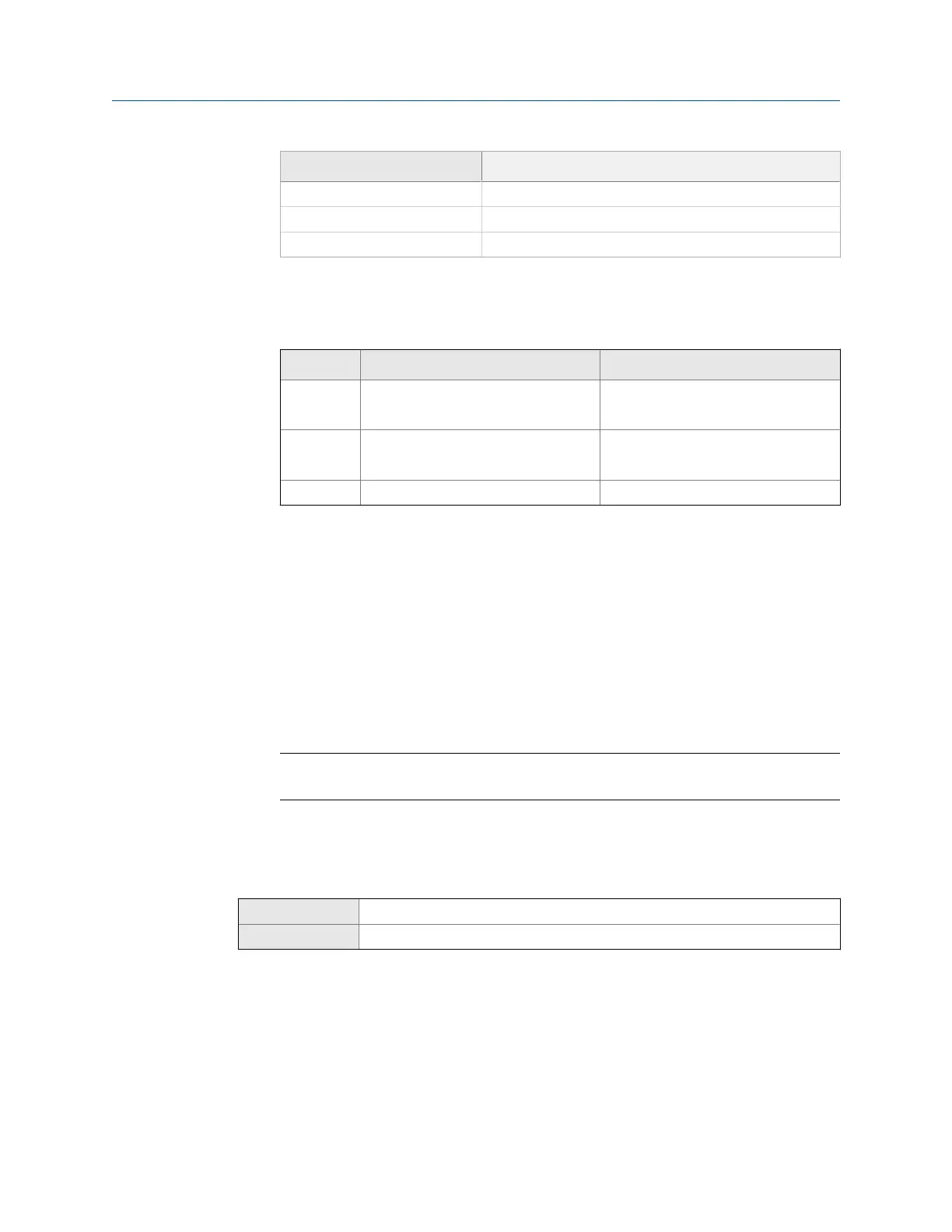
Bit structure of floating-point bytesTable 10-10:
Byte Bits Definition
1 SEEEEEEE S=Sign
E=Exponent
2 EMMMMMMM E=Exponent
M=Mantissa
3–4 MMMMMMMM M=Mantissa
4. (Optional) Set Additional Communications Response Delay in delay units.
A delay unit is 2/3 of the time required to transmit one character, as calculated for
the port currently in use and the character transmission parameters.
Additional Communications Response Delay is used to synchronize Modbus
communications with hosts that operate at a slower speed than the device. The
value specified here will be added to each response the device sends to the host.
• Default: 0
• Range: 0 to 255
Tip
Do not set Additional Communications Response Delay unless required by your Modbus host.
10.7
Configure Digital Communications Fault Action
ProLink III Device Tools > Configuration > Fault Processing
Field Communicator Configure > Alert Setup > I/O Fault Actions > Digital Communication Fault Action
Overview
Digital Communications Fault Action specifies the values that will be reported via digital
communications if the device encounters an internal fault condition.
Procedure
Set Digital Communications Fault Action as desired.
Integrate the meter with the control system
Configuration and Use Manual 115

 Loading...


