140 Functional description CG Drives & Automation 01-7492-01r1
Fig. 113 Upper band.
Lower Band [398]
If the speed of the master drive comes into the lower band
an additional drive will be stopped after a delay time. This
delay time is set in the parameter “Stop Delay [39A]”.
Example
Max Speed = 1500 rpm
Min Speed = 300 rpm
Lower Band = 10%
Stop delay will be activated:
Range = Max Speed - Min Speed = 1500–300 = 1200 rpm
10% of 1200 rpm = 120 rpm
Start level = 300 + 120 = 420 rpm
Fig. 114 Lower band.
Start Delay [399]
This delay time must have elapsed before the next pump is
started. A delay time prevents the nervous switching of
pumps.
Stop Delay [39A]
This delay time must have elapsed before the 'top' pump is
stopped. A delay time prevents the nervous switching of
pumps.
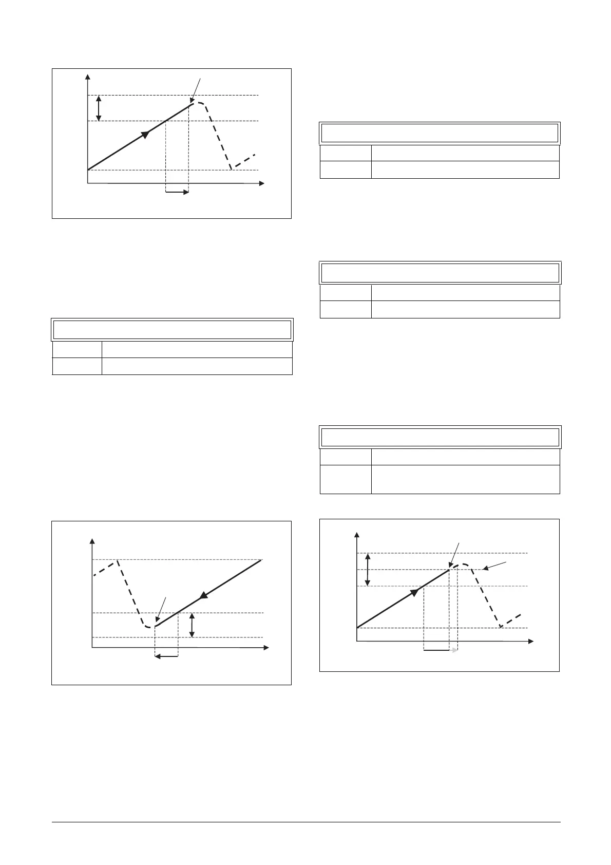
Upper Band Limit [39B]
If the speed of the pump reaches the upper band limit, the
next pump is started immediately without delay. If a start
delay is used this delay will be ignored. Range is between
0%, equalling max speed, and the set percentage for the
“UpperBand [397]”.
Fig. 115 Upper band limit.
398 Lower Band
Default: 10%
Range: 0-100% of total min speed to max speed
Flow/Pressure
Speed
Max
Min
Upper band
next pump starts
Start Delay [399]
(NG_50-PC-13_1)
Speed
Max
Min
“top” pump stops
Lower band
Stop Delay [39A]
Flow/Pressure
399 Start Delay
Default: 0 s
Range: 0-999 s
39A Stop Delay
Default: 0 s
Range: 0-999 s
39B Upp Band Lim
Default: 0%
Range:
0 to Upper Band level. 0% (=max speed)
means that the Limit function is switched off.
(NG_50-PC-14_2)
Speed
Max
Min
Upper band
Start Delay [399]
Upper band
limit [39B]
next pump starts
immediately
Flow/Pressure
 Loading...