176 CG Drives & Automation 01-7492-01r1
Timer 1 T2 [6515]
Timer 1 T2 sets the off time in the alternate mode.
Timer 1 Actual Value [6516]
Timer 1 Value shows actual value of the timer.
Timer 2 - Timer 4 [652] - [654]
Refer to the description for Timer 1 [651].
11.6.6 Flip flops [660]
The flip-flop function is a memory circuit that can be used
to store data concerning state. The output from a flip-flop is
dependent not only on its current input, but also on its state
at the moment this is received (hence previous input status
also matters).
The set/reset flip-flop circuit has two input signals, SET and
RESET, that control the state of an output signal, OUT.
When none of the input signals are active (i.e. both are =0),
the flip-flop will keep its current value. Changes of the flip-
flop state always occur on the rising edge of one of its inputs.
When only one of the input signals becomes active (=1), this
will directly decide the status of the output signal.
Consequently if SET becomes active and RESET is inactive,
the SET command is given to the output signal, OUT. This
will result in a signal change from inactive to active (=1), if
not already in an active state.
Conversely, if SET is inactive and RESET becomes active,
the RESET command is given to the output signal, OUT,
causing this to be deactivated (=0).
When both of the inputs signals becomes active the resulting
operation depends on the configured Flip-flop priority
mode as explained below.
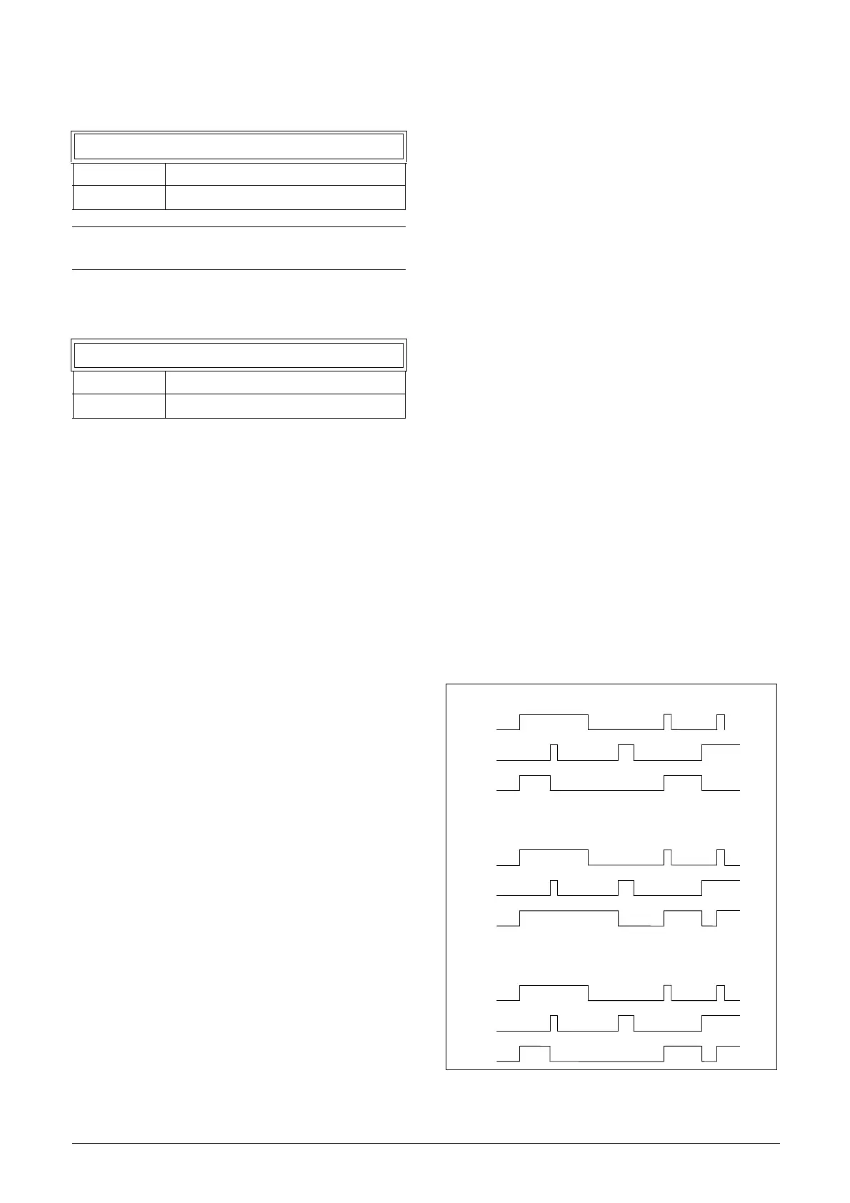
Flip-flop priority mode
When both input signals becomes active simultaneously, i.e.
both SET and RESET are =1, a priority function decides
which signal will influence the output signal. There are three
different priority settings available for the flip-flop function,
selected in the menu for "Flip-flop Mode". Examples of the
different priority settings are presented in fig. 140.
Fig. 140 Programmable flip-flop modes.
6515 Timer1 T2
Default: 0.0 s
Range: 0 - 36000.0 s
NOTE: “Timer 1 T1 [6514]” and “Timer 1 T2 [6515]”
are only visible when Timer Mode is set to Alternate.
6516 Timer1Value
Default: 0.0 s
Range: 0 - 36000.0 s
RESET
SET
OUT
RESET
SET
OUT
RESET
SET
OUT
Reset priority
Set priority
Edge controlled without priority

 Loading...

