54 Control Connections CG Drives & Automation 01-7492-01r1
4.5 Connecting the control
signals
4.5.1 Cables
The standard control signal connections are suitable for
stranded flexible wire up to 1.5 mm
2
(AWG16) and for solid
wire up to 2.5 mm
2
(AWG14).
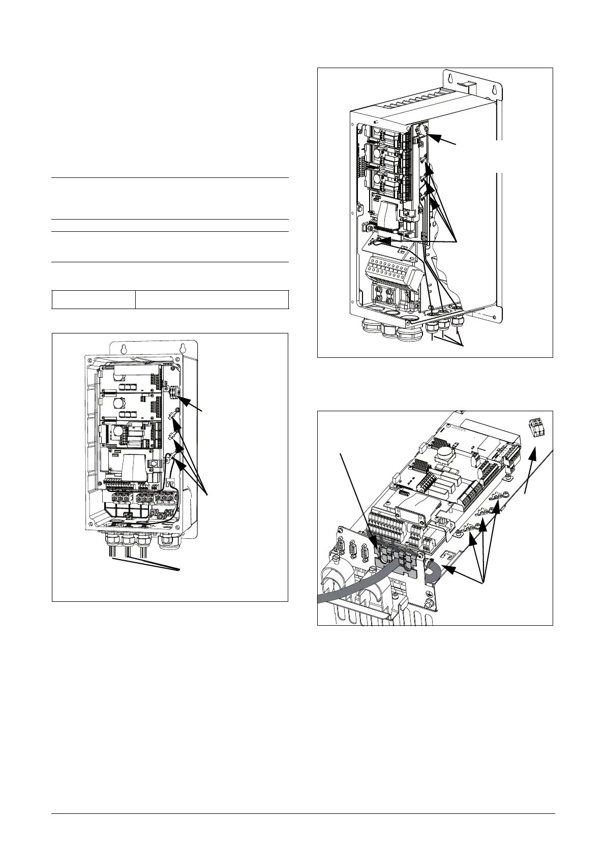
Fig. 64 Connecting the control signals, VFX model 003 to
018, frame size B.
Fig. 65 Connecting the control signals, VFX model 026 to
046, frame size C.
Fig. 66 Connecting the control signals, VFX model 48-025 to
48-058 frame size C2 and model 69-002 to 69-025
frame size C2(69).
NOTE: The screening of control signal cables must
comply with the immunity levels given in the EMC
Directive (reduction of noise level).
NOTE: The control cables must be separated from
motor and mains cables.
Table 25 Description of optional terminals in fig. 64 to fig. 68.
Terminals 78, 79 For connection of Motor PTC
Control signals
Terminals 78 & 79
see table 25
Screen clamps
for signal cables
Control signals
Terminal 78 & 79
see table 25
Screen clamps
for signal cables
motor PTC option
78 79
Feed-through of
signal cables
Screen clamps
for signal cables
See
table 25

 Loading...

