CG Drives & Automation 01-7492-01r1 Installation 35
Connect motor cables
1. Remove the cable interface plate from the AC drive
housing.
2. Put the cables through the glands.
3. Strip the cable according to table 15.
4. Connect the stripped cables to the respective motor
terminal.
5. Put the cable interface plate in place and secure
with the fixing screws.
6. Tighten the EMC gland with good electrical con-
tact to the motor and brake chopper cable screens.
Placing of motor cables
• Separate the power cables (AC drive, soft starter, output
coils, filters, magnetic switches, etc.) from the signal
cables (relay control circuit, PLC, sensors,
control PCBs, electronics, etc.).
• Keep the control cables as far from the power cables as
possible.
• If power cables and control cables must be laid close to
each other, try to ensure that they do not run parallel, at
least for a distance of no more than 300 mm (12 in).
If necessary, use a cable tray with a division or stack the
cable trays.
• Ensure that where power cables and control cables cross,
they do so at 90° to each other.
Long motor cables
If the connection to the motor is longer than 100 m
(330 ft) (for powers below 7.5 kW (10.2 hp)) please contact
CG Drives & Automation), it is possible that capacitive
current peaks will cause tripping at overcurrent. Using
output coils can prevent this. Contact the supplier for
appropriate coils.
Switching in motor cables
Switching in the motor connections is not advisable. In the
event that it cannot be avoided (e.g. emergency or
maintenance switches) only switch if the current is zero. If
this is not done, the AC drive can trip as a result of current
peaks.
3.3 Connection of motor and
mains cables for larger
frame sizes
IP54 - VFX 48-090 to 295 (Frame sizes E - F) and
VFX 48-365-54 (Frame size FA) and
VFX 69-082 to 200 (Frame size F69)
IP20 - VFX 48-430 and up (Frame sizes H and up) and
VFX 69-250 and up (Frame sizes H69 and up).
Emotron VFX48-090 to 48-295
Emotron VFX69-082 to 69-200
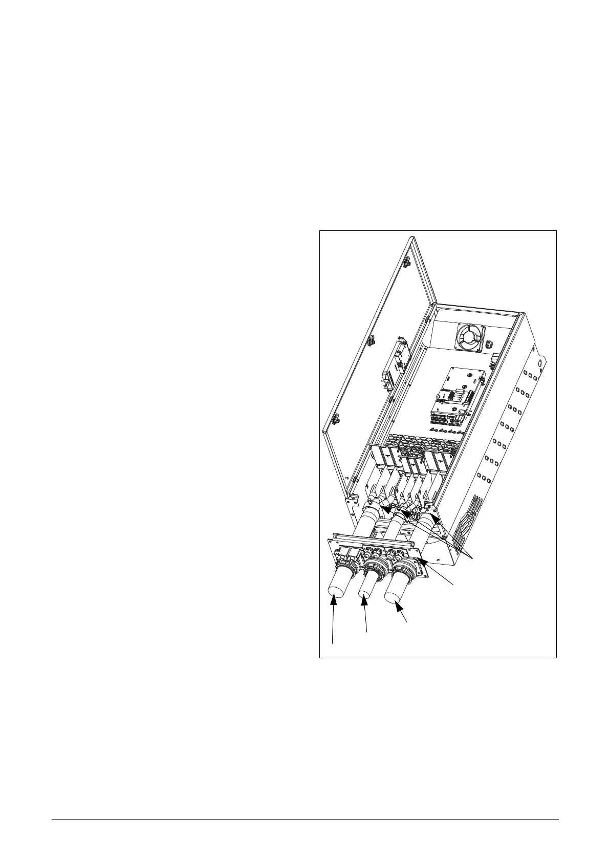
To simplify the connection of thick motor and mains cables
to the AC drive, the cable interface plate can be removed.
Fig. 50 Connecting motor and mains cables.
1. Remove the cable interface plate from the AC drive
housing.
2. Put the cables through the glands.
3. Strip the cable according to table 15.
4. Connect the stripped cables to the respective mains/
motor terminal.
5. Fix the clamps on appropriate place and tighten the
cable in the clamp with good electrical contact to
the cable screen.
6. Put the cable interface plate in place and secure
with the fixing screws.
Cable interface
Clamps for screening
Mains cable
DC+, DC-, R (optional)
Motor cable

 Loading...

