CG Drives & Automation 01-7492-01r1 Installation 33
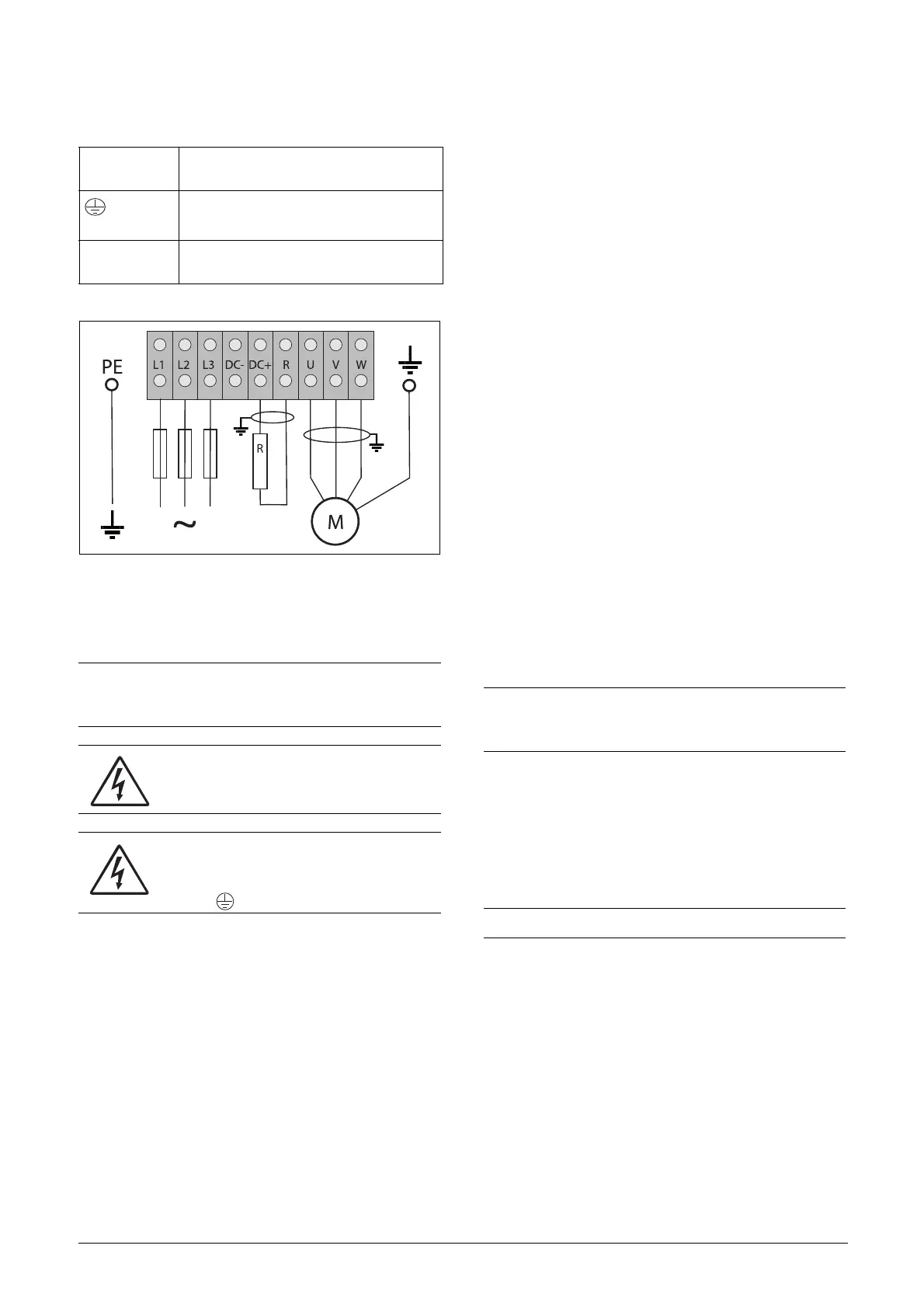
Fig. 46 Wiring example showing Protective earth, Motor earth
and Brake Resistor connection.
3.2.2 Motor cables
To comply with the EMC emission standards the AC drive
is provided with a RFI mains filter. The motor cables must
also be screened and connected on both sides. In this way a
so-called “Faraday cage” is created around the AC drive,
motor cables and motor. The RFI currents are now fed back
to their source (the IGBTs) so the system stays within the
emission levels.
Recommendations for selecting motor
cables
• Use screened cables according to specification in table
14. Use symmetrical shielded cable; three phase conduc-
tors and a concentric or otherwise symmetrically con-
structed PE conductor, and a shield.
• Use heat-resistant cables, +75 °C (167 °F) or higher.
• Dimension the cables in accordance with the rated
current of the motor.
• Keep the motor cable between AC drive and motor as
short as possible.
• The screening must be connected with a large contact
surface of preferable 360
° and always at both ends, to
the motor housing and the AC drive housing. When
painted mounting plates are used, scrape away the paint
to obtain as large blank contact surface as possible at all
mounting points for items such as saddles and the bare
cable screening. Relying just on the
connection made by the screw thread is not sufficient.
• The litz ground connection, see fig. 48, is only necessary
if the mounting plate is painted. All the AC drives have
an unpainted back side and are therefore suitable for
mounting on an unpainted mounting plate.
Connect the motor cables according to U - U, V - V and
W - W, see fig. 37, to fig. 45.
Table 13 Mains and motor connections
L1,L2,L3
PE
Mains supply, 3 -phase
Safety earth (protected earth)
U, V, W
Motor earth
Motor output, 3-phase
DC-,DC+,R
Brake resistor, DC-link
connections (optional)
NOTE: The Brake and DC-link Terminals are only
fitted if the DC+/DC- option or Brake Chopper Option
is built-in.
WARNING!
The Brake Resistor must be connected
between terminals DC+ and R.
WARNING!
In order to work safely, the mains earth
must be connected to PE and the motor
earth to .
NOTE: It is important that the motor housing has the
same earth potential as the other parts of the
machine.
NOTE: The terminals DC-, DC+ and R are options.

 Loading...

