50 Control Connections CG Drives & Automation 01-7492-01r1
4.2 Terminal connections
The terminal strip for connecting the control signals is
accessible after opening the front panel.
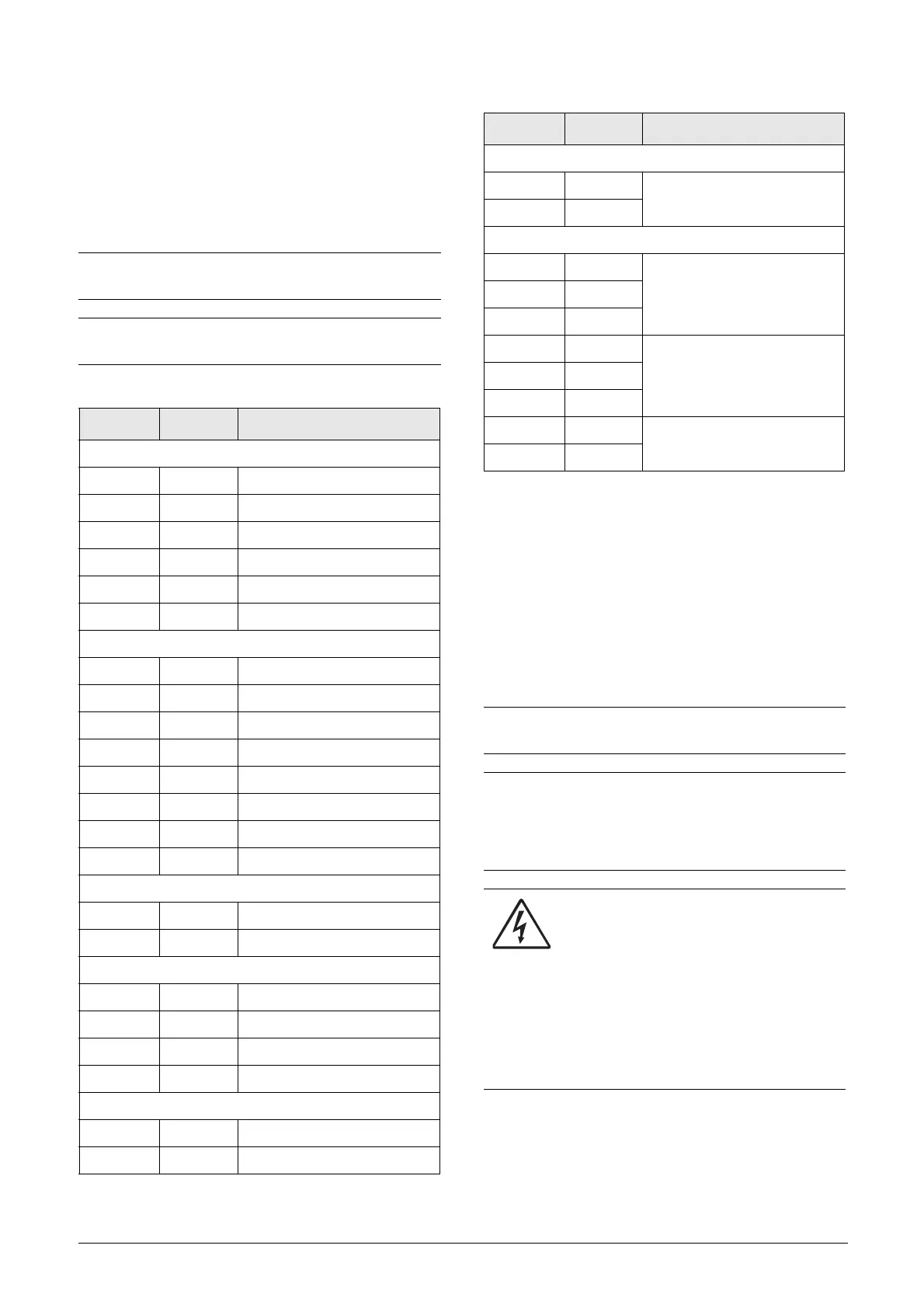
The table describes the default functions for the signals. The
inputs and outputs are programmable for other functions as
described in chapter 11. page 87. For signal specifications
refer to chapter 14. page 207.
* Digital signal ground connected to 0V via ferrite (600 Ohm @ 100MHz).
1
The integrated RS-485 interface is a isolated interface
supporting Modbus RTU protocol with baudrates ranging from
2400 bit/s up to 115.2 kbit/s. Termination and fail-safe can be acti-
vated via switch S5 when applicable. Note that proper termination and
fail-safe is critical for a stable RS-485 network. It is recommended to
use screened RS-485 cable which protects the signals from EMI. The
cable screen should (in normal cases) be connected to inverter PE via
provided screen clamps, see fig. 63. For further information about
Modbus RTU protocol and physical network connection see Emotron
option manual for Serial communication RS-232/485 available on our
website.
NOTE: The maximum total combined current for
outputs 11, 20 and 21 is 100mA.
NOTE: It is possible to use external 24V DC if
connection to Common (15).
Table 21 Control signals
Ter min al Name Function (Default)
Outputs
1 +10 V +10 VDC supply voltage
6 -10 V -10 VDC supply voltage
7 Common Signal ground
11 +24 V +24 VDC supply voltage
12 Common Signal ground
15 Common Dig signal ground *
Digital inputs
8 DigIn 1 RunL (reverse)
9 DigIn 2 RunR (forward)
10 DigIn 3 Off
16 DigIn 4 Off
17 DigIn 5 Off
18 DigIn 6 Off
19 DigIn 7 Off
22 DigIn 8 RESET
Digital outputs
20 DigOut 1 Ready
21 DigOut 2 Brake
Analogue inputs
2 AnIn 1 Process Ref
3AnIn 2Off
4AnIn 3Off
5AnIn 4Off
Analogue outputs
13 AnOut 1 Min speed to max speed
14 AnOut 2 0 to max torque
Integrated RS-485
1
A+ A+
RS-485 Differential transmit
and receive
B- B-
Relay outputs
31 N/C 1
Relay 1 output
Trip, active when the AC drive
is in a TRIP condition.
32 COM 1
33 N/O 1
41 N/C 2
Relay 2 output
Run, active when the AC
drive is started.
42 COM 2
43 N/O 2
51 COM 3
Relay 3 output
Off
52 N/O 3
NOTE: N/C is opened when the relay is active and
N/O is closed when the relay is active.
NOTE! Using potentiometer for reference signal to
Analogue input: Possible potentiometer value in
range of 1 kΩ to 10 kΩ (¼ Watt) linear, where we
advice to use a linear 1 kΩ / ¼ W type potentiometer
for best control linearity.
WARNING!
The relay terminals 31-52 are single
isolated. Do NOT mix SELV voltage with
e.g. 230 VAC on these terminals. A solution
when dealing with mixed SELV/system
voltage signals is to install an additional I/
O board option (see section 13.8 page 204)
and connect all SELV voltage signals to the
relay terminals of this option board while
connecting all 230VAC signals to the
control board relay terminals 31 - 52.
Table 21 Control signals
Term i n al Name Function (Default)

 Loading...

