204 Options CG Drives & Automation 01-7492-01r1
The brake chopper option is built-in by the manufacturer
and must be specified when the AC drive is ordered.
13.8 I/O Board
Each I/O option board 2.0 provides three extra relay outputs
and three extra isolated digital inputs (24V). The I/O Board
works in combination with the Pump/Fan Control, but can
also be used as a separate option. Maximum 3 I/O boards
possible. This option is described in a separate manual.
13.9 Encoder
The Encoder 2.0 option board, used for connection of
feedback signal of the actual motor speed via an incremental
encoder is described in a separate manual.
For Emotron FDU and for VFX in V/Hz mode this
function is for speed read-out only or for spin start function.
No speed control.
13.10 PTC/PT100
The PTC/PT100 2.0 option board for connecting motor
thermistors and max 3 PT100 elements to the AC drive is
described in a separate manual.
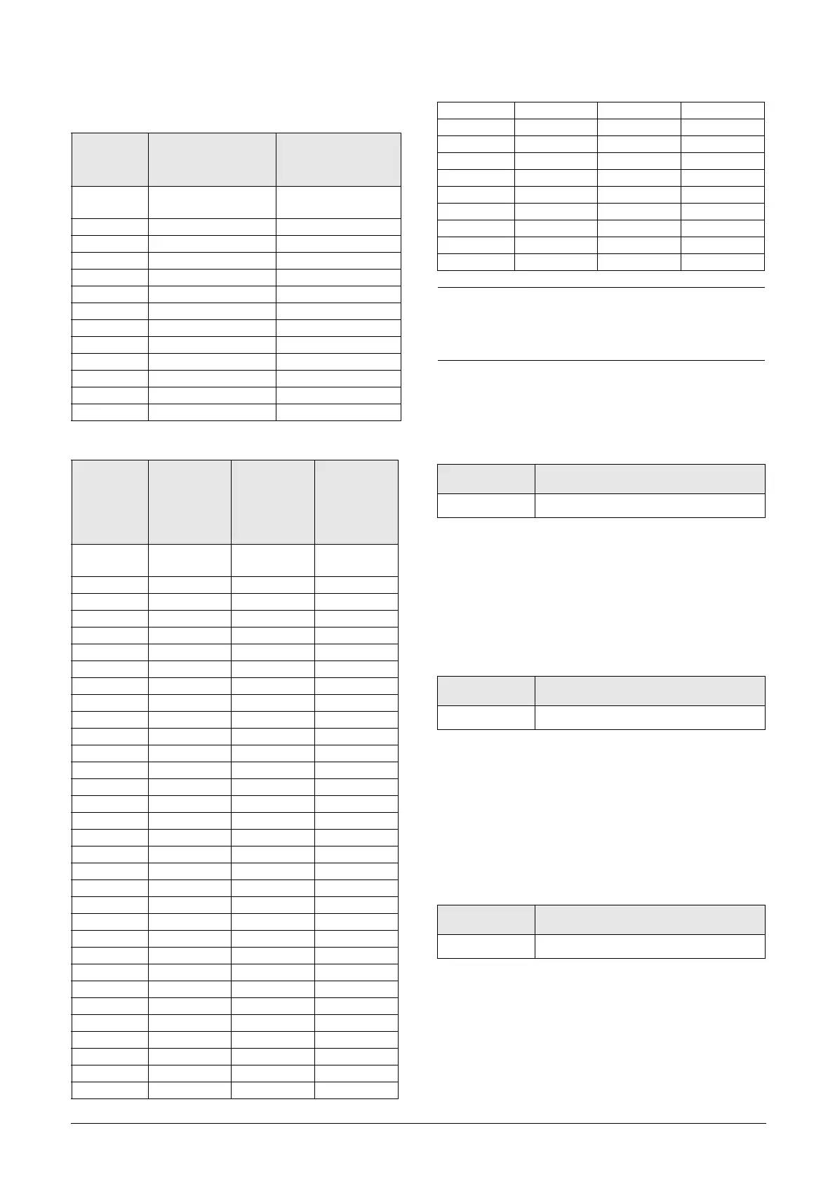
Table 48 Brake resistor VFX52 V types
Type
Rmin [ohm] if
supply 440–480
V
AC
Rmin [ohm] if
supply 500–525
V
AC
VFX52-
003
50 55
-004 50 55
-006 50 55
-008 50 55
-010 50 55
-013 50 55
-018 50 55
-026 30 32
-031 30 32
-037 20 22
-046 20 22
-061 12 14
-074 12 14
Table 49 Brake resistor VFX69 V types
Typ e
Rmin
[ohm]
if supply
500–525
V
AC
Rmin [ohm]
if supply
550–600
V
AC
Rmin [ohm]
if supply
660–690
V
AC
VFX69-
002
30.4 34.8 40.0
-003 30.4 34.8 40.0
-004 30.4 34.8 40.0
-005 30.4 34.8 40.0
-008 30.4 34.8 40.0
-010 30.4 34.8 40.0
-013 30.4 34.8 40.0
-018 30.4 34.8 40.0
-021 30.4 34.8 40.0
-025 30.4 34.8 40.0
-033 12.9 14.8 17.0
-042 12.9 14.8 17.0
-050 12.9 14.8 17.0
-058 12.9 14.8 17.0
-082 4.9 5.7 6.5
-090 4.9 5.7 6.5
-109 4.9 5.7 6.5
-146 4.9 5.7 6.5
-175 4.9 5.7 6.5
-200 4.9 5.7 6.5
-250 2 x 4.9 2 x 5.7 2 x 6.5
-300 2 x 4.9 2 x 5.7 2 x 6.5
-375 2 x 4.9 2 x 5.7 2 x 6.5
-400 2 x 4.9 2 x 5.7 2 x 6.5
-430 3 x 4.9 3 x 5.7 3 x 6.5
-500 3 x 4.9 3 x 5.7 3 x 6.5
-595 3 x 4.9 3 x 5.7 3 x 6.5
-650 4 x 4.9 4 x 5.7 4 x 6.5
-720 4 x 4.9 4 x 5.7 4 x 6.5
-800 4 x 4.9 4 x 5.7 4 x 6.5
-905 5 x 4.9 5 x 5.7 5 x 6.5
-995 5 x 4.9 5 x 5.7 5 x 6.5
-1K2 6 x 4.9 6 x 5.7 6 x 6.5
-1K4 7 x 4.9 7 x 5.7 7 x 6.5
-1K6 8 x 4.9 8 x 5.7 8 x 6.5
-1K8 9 x 4.9 9 x 5.7 9 x 6.5
-2K0 10 x 4.9 10 x 5.7 10 x 6.5
-2K2 11 x 4.9 11 x 5.7 11 x 6.5
-2K4 12 x 4.9 12 x 5.7 12 x 6.5
-2K6 13 x 4.9 13 x 5.7 13 x 6.5
-2K8 14 x 4.9 14 x 5.7 14 x 6.5
-3K0 15 x 4.9 15 x 5.7 15 x 6.5
NOTE: Although the AC drive will detect a failure in
the brake electronics, the use of resistors with a
thermal overload which will cut off the power at
overload is strongly recommended.
Part number Description
01-3876-01 I/O option board 2.0
Part number Description
01-3876-03 Encoder 2.0 option board
Part number Description
01-3876-08 PTC/PT100 2.0 option board
Table 49 Brake resistor VFX69 V types

 Loading...

