178 CG Drives & Automation 01-7492-01r1
Flip flop 1 reset delay [6615]
The RESET input signal for flip-flop 1 is delayed with the
set value in this menu.
Flip flop 1 timer value [6616]
This menu shows the actual value of the flip flop 1 timer.
Flip flop 2 - 4 [662] - [664]
Refer to the description for Flip Flop 1[661].
11.6.7 Counters [670]
Counter functions for counting pulses and signalling on
digital output when counter reaches specified high and low
limit levels.
The counter is counting up on positive flanks on the
triggered signal, the counter is cleared as long as the Reset
signal is active.
The counter can be automatically decremented with
specified decrement time, if no new trigger signal has
occurred within the decrement time.
The counter value is clamped to the high limit value and the
digital output function (CTR1 or CTR2) is active when
counter value equals high limit value.
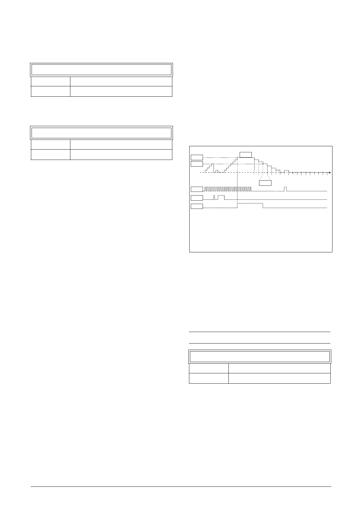
See fig. 141 for more information of the counters.
Fig. 141 Counters, operating principle.
Counter1 [671]
Counter 1 parameter group.
Counter 1 Trigger [6711]
Selection of the digital output signal used as trigger signal
for counter 1. Counter 1 is incremented by 1 on every
positive flank on the trigger signal.
6615 F1 Res Dly
Default: 0.0 s
Selection: 0 - 36000.0 s
6616 F1 Tmr Val
Default: 0.0 s
Selection: 0 - 36000.0 s
NOTE: Maximum counting frequency is 8 Hz.
6711 C1 Trig
Default: Off
Selection: Same as in menu DigOut 1
[541].
6619
6615
6614
6611
6612
541
541 = Digital Out 1 function
6611= Counter 1 trigger
6612= Counter 1 reset
6613= Counter 1 High value
6614= Counter 1 Low value
6615= Counter 1 Decrement timer
6619= Counter 1 value
6613

 Loading...

