CG Drives & Automation 01-7492-01r1 Installation 39
3.4 Cable specifications
3.4.1 Stripping lengths
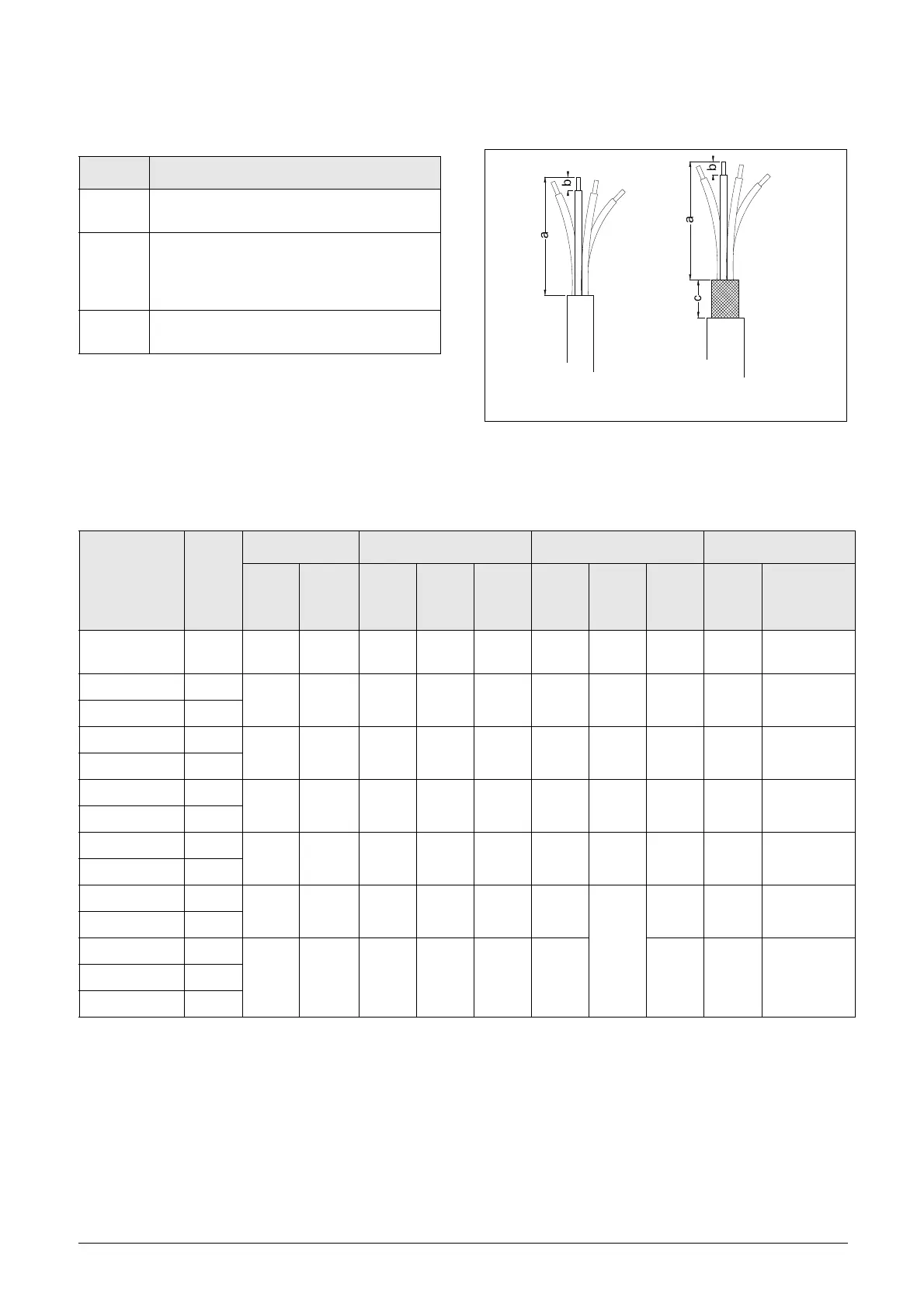
Fig. 59 indicates the recommended stripping lengths for
motor and mains cables.
Fig. 59 Stripping lengths for cables
* Cable lug.
** Valid when brake chopper electronics are built in
Table 14 Cable specifications
Cable Cable specification
Mains
Power cable suitable for fixed installation for the
voltage used.
Motor
Symmetrical three conductor cable with
concentric protection (PE) wire or a four
conductor cable with compact low-impedance
concentric shield for the voltage used.
Control
Control cable with low-impedance shield,
screened.
Table 15 Stripping lengths for mains, motor, brake and earth cables for frame sizes B to F
Model VFX
Frame
size
Mains cable Motor cable Brake cable Earth cable
a
mm
(in)
b
mm
(in)
a
mm
(in)
b
mm
(in)
c
mm
(in)
a
mm
(in)
b
mm
(in)
c
mm
(in)
a
mm
(in)
b
mm (in)
##-003 – 018 B
90
(3.5)
10 (0.4) 90 (3.5)
10
(0.4)
20
(0.8)
90 (3.5)
10
(0.4)
20
(0.8)
90 (3.5) 10 (0.4)
##-026 – 046 C
150
(5.9)
14 (0.2)
150
(5.9)
14
(0.2)
20
(0.8)
150
(5.9)
14
(0.2)
20
(0.8)
150
(5.9)
14 (0.2)
69-002 – 025 C69
69-002 – 025 C2(69)
65
(2.7)
18 (0.7) 65 (2.7)
18
(0.7)
36
(1.4)
65 (2.7)
18
(0.7)
36
(1.4)
65 (2.7) M6 screw*
48-025 – 058 C2
##-061 – 074 D
110
(4.3)
17 (0.7)
110
(4.3)
17
(0.7)
34
(1.4)
110
(4.3)
17
(0.7)
34
(1.4)
110
(4.3)
17 (0.7)
69-033 – 058 D69
69-033 – 058 D2(69)
92
(3.6)
18 (0.7) 92 (3.6)
18
(0.7)
36
(1.4)
92 (3.6)
18
(0.7)
36
(1.4)
92 (3.6) M6 screw*
48-060 – 105 D2
##-090 – 175 E
173
(6.8)
25 (1)
173
(6.8)
25 (1)
41
(1.6)
173
(6.8)
25 (1)
41
(1.6)
173
(6.8)
25 (1)
40 (1.6)**
48-142 – 171 E2
48-205 – 293 F2
178 (7) 32 (1.3) 178 (7)
32
(1.3)
46
(1.8)
178 (7)
46
(1.8)
178 (7)
32 (1.3)
40 (1.6)**
48-210 – 295 F
69-082 – 200 F69

 Loading...

