160 CG Drives & Automation 01-7492-01r1
AnOut2 Setup [535]
Preset scaling and offset of the output configuration for
analogue output 2.
AnOut2 Advanced [536]
Same functions and submenus as under AnOut1 Advanced
[533].
11.5.4 Digital Outputs [540]
Submenu with all the settings for the digital outputs.
Digital Out 1 [541]
Sets the function for the digital output 1.
535 AnOut2 Setup
Default: 4-20mA
Selection: Same as in menu
[512]
536 AnOut2 Advan
NOTE: The definitions described here are valid for the
active output condition.
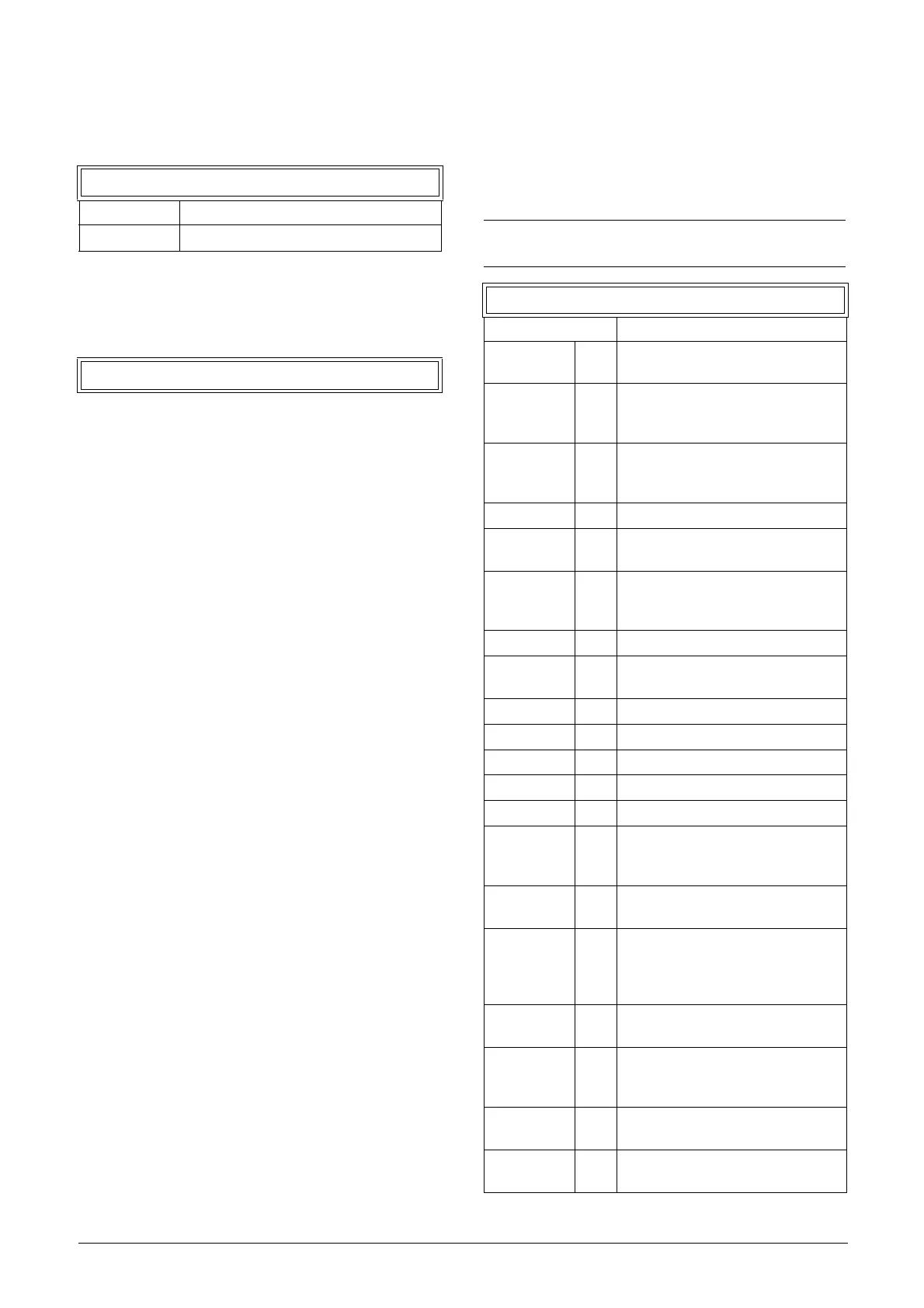
541 DigOut 1
Default: Ready
Off 0
Output is not active and constantly
low.
On 1
Output is made constantly high, i.e.
for checking circuits and trouble
shooting.
Run 2
Running. The AC drive output is
active = produces current for the
motor.
Stop 3 The AC drive output is not active.
0Hz 4
The output frequency=0±0.1Hz
when in Run condition.
Acc/Dec 5
The speed is increasing or
decreasing along the acc. ramp dec.
ramp.
At Process 6 The output = Reference.
At Max spd 7
The frequency is limited by the
Maximum Speed.
No Trip 8 No Trip condition active.
Trip 9 A Trip condition is active.
AutoRst Trip 10 Autoreset trip condition active.
Limit 11 A Limit condition is active.
Warning 12 A Warning condition is active.
Ready 13
The AC drive is ready for operation.
This means that the AC drive is
powered up and healthy.
T= T
lim
14
The torque is limited by the torque
limit function.
I>I
nom
15
The output current is higher than the
motor nominal current [224], reduced
according to Motor ventilation [228],
see fig. 92, page 95.
Brake 16
The output is used to control a
mechanical brake.
AnIn<Offset 17
One of the AnIn input signals is lower
than 75% of the configured minimum
value.
Alarm 18
The max or min alarm level has been
reached.
Pre Alarm 19
The max or min pre alarm level has
been reached.

 Loading...

