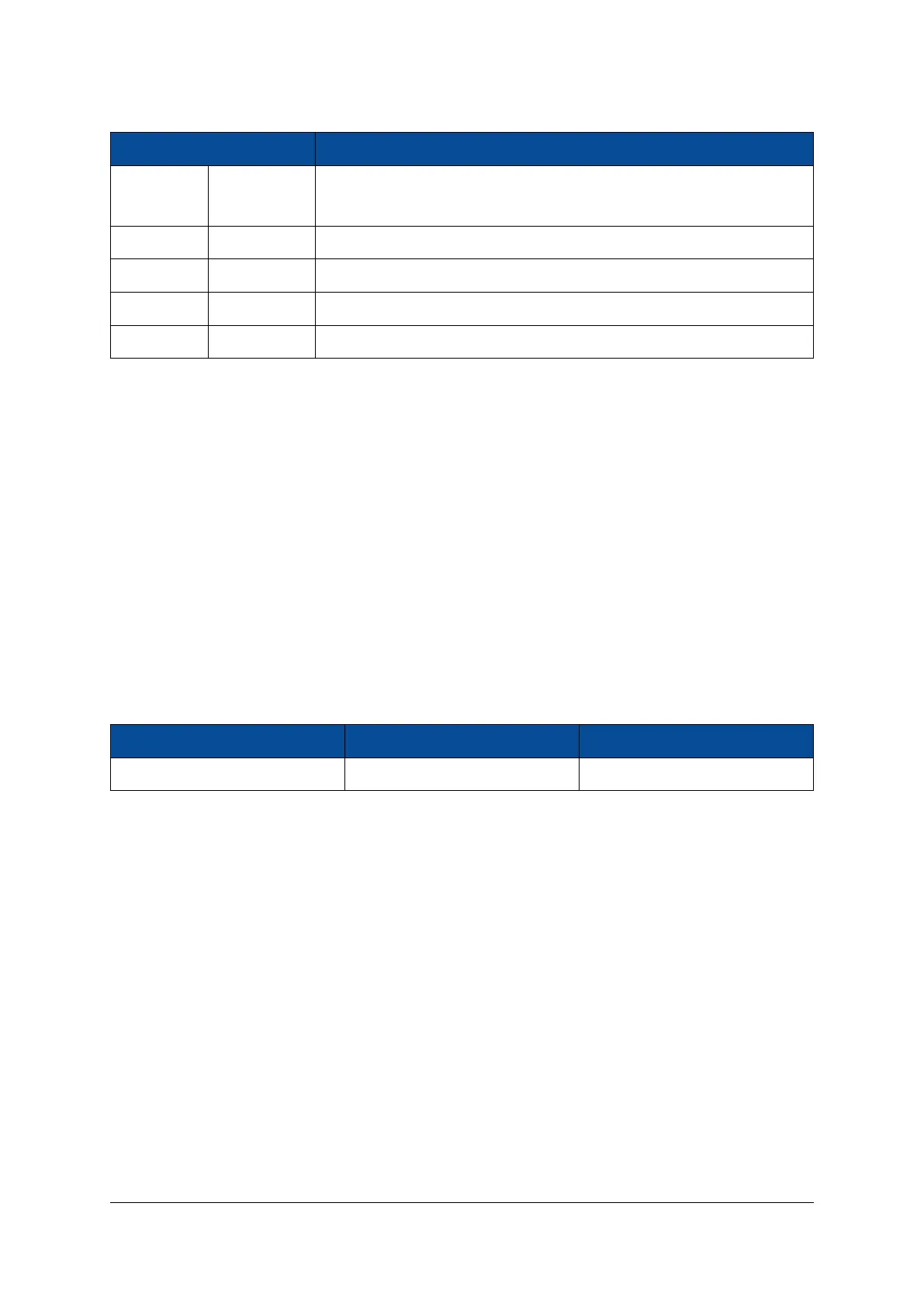
Pin Signal Value Description
MODE[3-0] 1110 RGMII mode: advertise all capabilities (10/100/1000, half/full duplex) ex-
cept 1000Base-T half duplex.
PHYAD[2-0] 011 MDIO address 3
Clk125_EN 0 125 MHz clock output disabled
LED_MODE 1 Single LED mode
LED1/LED2 1 Active-low LEDs
Table 31: Gigabit Ethernet PHY Configuration
For the Ethernet PHY configuration via the MDIO interface, the MDC clock frequency must not exceed 1
MHz.
2.21 Dual Fast Ethernet
There are two 10/100 Mbit Ethernet PHYs equipped on the Mercury ZX1 SoC module, connected to FPGA
I/Os via MII interface.
On Mercury ZX1 SoC modules revision 1 the Fast Ethernet ports are not enabled when DDR3 SDRAM is
operated in low power mode. This is because the Ethernet ports are fed by the same supply as the DDR3
memory and require a voltage of 1.5 V to work properly. This issue has been fixed for modules from revision
2 and newer.
2.21.1 Ethernet PHY Type
Table 32 describes the equipped Ethernet PHY device type on the Mercury ZX1 SoC module.
PHY Type Manufacturer Type
TLK105LRHBR Texas Instruments 10/100 Mbit
Table 32: Fast Ethernet PHY Type
2.21.2 Signal Description
The MII interfaces are connected to the FPGA pins in banks 12 and 34 for use with soft Ethernet MAC IP
cores. The signals connected to I/O bank 34 have 4.7 kΩ series resistors as protection if low I/O voltages
are used. The two Fast Ethernet PHYs have a shared MDIO interface and a shared interrupt line. Details on
connections are available in the Mercury ZX1 SoC Module User Schematics [5] and in the FPGA Pinout Excel
Sheet [4].
The 25 MHz clock for the Fast Ethernet must be supplied via FPGA pin W14.
Some of the MII signals have pull-up or pull-down resistors for bootstrapping. Make sure all FPGA internal
resistors are disabled.
The reset signal of the Fast Ethernet PHYs has a pull-down resistor and is connected to FPGA pin AF14. It
needs to be driven high to release the PHYs from reset.
D-0000-403-002 38 / 56 Version 05, 25.07.2019

 Loading...

