Signal SoC Mod. Description Comments
Name Pin Type Conn. Pin
BOOT_MODE1 - A-112 Boot mode selection
10 kΩ pull-up to
VCC_CFG_MIO_B12
Table 37: SoC Configuration Pins
Warning!
All configuration signals except for BOOT_MODE must be high impedance as soon as the device is
released from reset. Violating this rule may damage the equipped SoC device, as well as other devices
on the Mercury ZX1 SoC module.
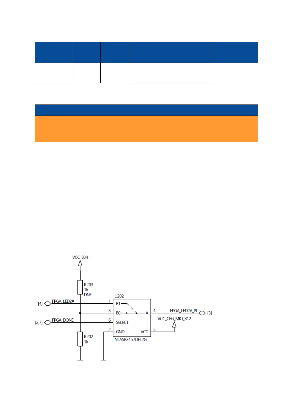
3.2 Pull-Up During Configuration
The Pull-Up During Configuration signal (PUDC) is pulled to ground via a 1 kΩ resistor during FPGA config-
uration, and connected to an FPGA signal after this process is done.
As PUDC is an active-low signal, all FPGA I/Os will have the internal pull-up resistors enabled during device
configuration.
If the application requires that all FPGA I/Os have the internal pull-up resistors disabled during device con-
figuration, this can be achieved by removing R202 component and by mounting R203 - in this configuration
the PUDC pin is connected to VCC_IO_B34.
Figure 11 illustrates the configuration of the I/O signals during power-up. Figure 12 indicates the location of
the pull-up/pull-down resistors on the module PCB - upper right part on the top view drawing and upper
left part on the bottom view drawing.
Figure 11: Pull-Up During Configuration (PUDC)
D-0000-403-002 42 / 56 Version 05, 25.07.2019

 Loading...

