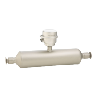
Proline Promass E 300 PROFINET Commissioning
Endress+Hauser 137
Parameter Prerequisite Description Selection / User entry /
User interface
Pulse output simulation 1 to n In the Operating mode parameter, the
Pulse option is selected.
Set and switch off the pulse output
simulation.
For Fixed value option: Pulse
width parameter (→ 103)
defines the pulse width of the
pulses output.
• Off
• Fixed value
• Down-counting value
Pulse value 1 to n In the Pulse output simulation 1 to n
parameter, the Down-counting value
option is selected.
Enter the number of pulses for
simulation.
0 to 65 535
Switch output simulation 1 to n In the Operating mode parameter, the
Switch option is selected.
Switch the simulation of the switch
output on and off.
• Off
• On
Switch status 1 to n – Select the status of the status output for
the simulation.
• Open
• Closed
Relay output 1 to n simulation – Switch simulation of the relay output
on and off.
• Off
• On
Switch status 1 to n The On option is selected in the Switch
output simulation 1 to n parameter
parameter.
Select status of the relay output for the
simulation.
• Open
• Closed
Pulse output simulation – Set and switch off the pulse output
simulation.
For Fixed value option: Pulse
width parameter defines the
pulse width of the pulses output.
• Off
• Fixed value
• Down-counting value
Pulse value In the Pulse output simulation
parameter, the Down-counting value
option is selected.
Set and switch off the pulse output
simulation.
0 to 65 535
Device alarm simulation – Switch the device alarm on and off. • Off
• On
Diagnostic event category – Select a diagnostic event category. • Sensor
• Electronics
• Configuration
• Process
Diagnostic event simulation – Select a diagnostic event to simulate
this event.
• Off
• Diagnostic event picklist
(depends on the category
selected)
Logging interval – Define the logging interval tlog for data
logging. This value defines the time
interval between the individual data
points in the memory.
1.0 to 3 600.0 s
* Visibility depends on order options or device settings
10.8 Protecting settings from unauthorized access
The following write protection options exist in order to protect the configuration of the
measuring device from unintentional modification:
• Protect access to parameters via access code → 138
• Protect access to local operation via key locking → 61
• Protect access to measuring device via write protection switch → 139
• Protect access to parameters via startup configuration → 86

 Loading...


