Proline Promass E 300 PROFINET Technical data
Endress+Hauser 245
If the device is fitted with a rupture disk (order code for "Sensor option", option CA "Rupture
disk"), the rupture disk trigger pressure is decisive .
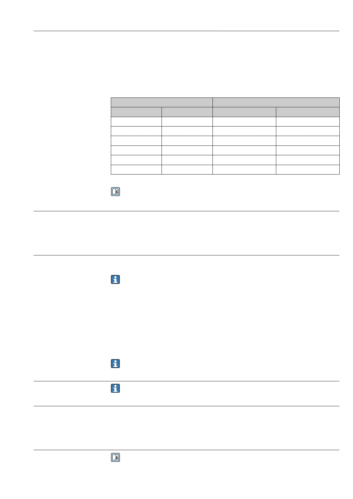
The sensor housing burst pressure refers to a typical internal pressure which is reached
prior to mechanical failure of the sensor housing and which was determined during type
testing. The corresponding type test declaration can be ordered with the device (order code
for "Additional approval", option LN "Sensor housing burst pressure, type test").
DN Sensor housing burst pressure
[mm] [in] [bar] [psi]
8 ³⁄₈ 250 3 620
15 ½ 250 3 620
25 1 250 3 620
40 1½ 200 2 900
50 2 180 2 610
80 3 120 1 740
For information on the dimensions: see the "Mechanical construction" section of the
"Technical Information" document
Rupture disk To increase the level of safety, a device version with a rupture disk with a trigger pressure
of 10 to 15 bar (145 to 217.5 psi)can be used (order code for "Sensor option", option CA
"rupture disk").
The use of rupture disks cannot be combined with the separately available heating jacket.
Flow limit Select the nominal diameter by optimizing between the required flow range and
permissible pressure loss.
For an overview of the full scale values for the measuring range, see the "Measuring
range" section → 229
• The minimum recommended full scale value is approx. 1/20 of the maximum full scale
value
• In most applications, 20 to 50 % of the maximum full scale value can be considered ideal
• A low full scale value must be selected for abrasive media (such as liquids with entrained
solids): flow velocity < 1 m/s (< 3 ft/s).
• For gas measurement the following rules apply:
• The flow velocity in the measuring tubes should not exceed half the sound velocity
(0.5 Mach).
• The maximum mass flow depends on the density of the gas: formula → 229
To calculate the flow limit, use the Applicator sizing tool → 227
Pressure loss To calculate the pressure loss, use the Applicator sizing tool → 227
System pressure → 24
16.10 Mechanical construction
Design, dimensions
For the dimensions and installation lengths of the device, see the "Technical
Information" document, "Mechanical construction" section.