Electrical connection Proline Promass E 300 PROFINET
34 Endress+Hauser
2. If the measuring device is supplied without cable glands:
Provide suitable cable gland for corresponding connecting cable.
3. If the measuring device is supplied with cable glands:
Observe requirements for connecting cables → 30.
7.2 Connecting the measuring device
NOTICE
Limitation of electrical safety due to incorrect connection!
‣
Have electrical connection work carried out by appropriately trained specialists only.
‣
Observe applicable federal/national installation codes and regulations.
‣
Comply with local workplace safety regulations.
‣
Always connect the protective ground cable before connecting additional cables.
‣
For use in potentially explosive atmospheres, observe the information in the device-
specific Ex documentation.
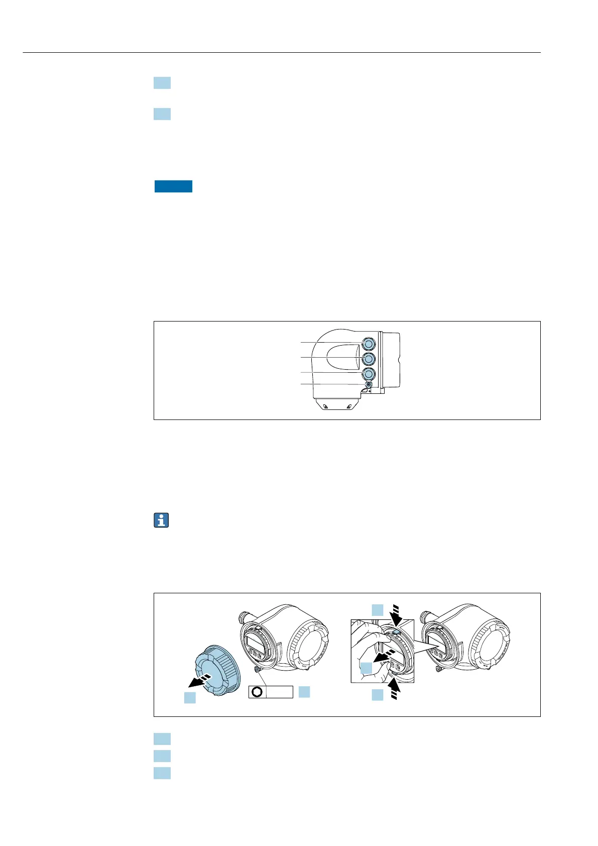
7.2.1 Connecting the transmitter
A0026781
1 Terminal connection for supply voltage
2 Terminal connection for signal transmission, input/output
3 Terminal connection for signal transmission, input/output or terminal connection for network connection via
service interface (CDI-RJ45); optional: connection for external WLAN antenna or remote display and
operating module DKX001
4 Protective earth (PE)
In addition to connecting the device via PROFINET and the available inputs/outputs,
additional connection options are also available:
• Integrate into a network via the service interface (CDI-RJ45) → 38.
• Integrate the device into a ring topology → 39.
Connecting the PROFINET connector
N
i
c
h
t
u
n
t
e
r
a
r
e
ö
f
f
n
e
n
+
E
ESC
–
1.
2.
N
i
c
h
t
u
n
t
e
r
a
r
e
ö
f
f
n
e
n
+
E
ESC
–
+
E
ESC
–
3.
3.
4.
3 mm
A0029813
1. Loosen the securing clamp of the connection compartment cover.
2. Unscrew the connection compartment cover.
3. Squeeze the tabs of the display module holder together.