3 Installation PROline Prosonic Flow 93 PROFIBUS-DP/-PA
26 Endress+Hauser
2. Set the sensor distance on the sensor assembly by moving the sensors (c) along
the assembly frame and tightening the sensor fixing nuts (d). Preferably, the sensor
position is set symmetrically to the rail centre.
Turn the sensor adjustment screw counter-clockwise (e) so that the sensor moves
upwards inside the assembly frame. Coat the sensors with coupling fluid as
explained on Page 82.
Abb. 21: Preparing the sensor assembly for the installation
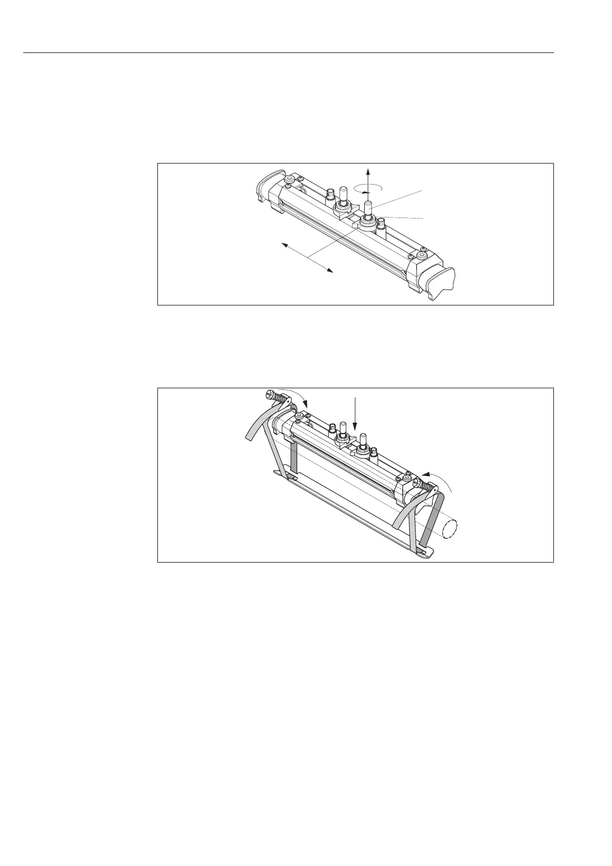
3. Then position the sensor assembly (f) on the pipe. Guide the tensioning bands over
the ends of the sensor assembly (g) and pull the bands tight by hand (please note
that the screw of the tensioning band lock must be opened).
Abb. 22: Positioning the sensor and looping the tensioning bands
c
d
e
F06-9xUxxxxx-17-05-06-xx-004
g
g
f
F06-9xUxxxxx-17-05-06-xx-001