PROline Prosonic Flow 93 PROFIBUS-DP/-PA 4 Wiring
Endress+Hauser 43
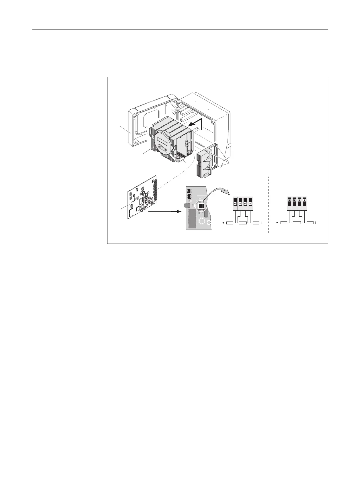
6. Use a pointed object to adjust the positions of the miniature switches on the
I/O board.
7. Installation is the reverse of the removal procedure.
Fig. 46: Setting the terminating resistors (PROFIBUS-DP)
A = Factory setting
B = Setting on the last transmitter
In addition, pay attention to the following points:
For baud rates of up to 1.5 MBaud, terminate the last transmitter on the bus by setting
the terminator switches SW 1 to: ON – ON – ON – ON.
If the device is to be operated at over 1.5 MBaud, you can tap the power supply for
an external terminator from terminals 24 (GND) and 25 (+5 V), see Page 49.
If the device is to be operated at a baud rate >1.5 MBaud, an external terminator is
necessary, e.g. with a 9-pin Sub D cable connector combination, with an integrated
series inductance to compensate for the station's capacitive load and minimise the
resulting line reflections.
!
Note!
As a rule, we recommend that an external terminator be used, since a defect in an
internally terminated device can disrupt the entire segment.
1
2
5
6
34
1
2
O N
34
390 Ω
SW 1
220 Ω
390 Ω
+5V
ON
OFF
4
3
2
1
A
SW 1
390 Ω
220 Ω
390 Ω
+5V
ON
OFF
4
3
2
1
B
F06-xxxPBxxx-16-xx-xx-xx-004