Enertech Global, LLC 22
AV : MD/ME - Rev. A Models
Installaon and Operaons Manual
Successful design of the system must also include pipe
diameter and layout. The following guidelines should be
considered for all hydronic designs:
• Proper Flow Rate: There could be two dierent ow rates
on each side of the Indoor Module, depending upon the
size and number of zones and the size of the heat pump.
Supply/return lines for the heat pump side of the Indoor
Module must be sized for the heat pump ow rate;
supply/return lines on the system pump side of the Indoor
Module must be sized based upon the number and size of
connected zones.
• Supply/Return Pipe Diameter: Any hydronic system with
parallel piping to various zones requires large enough
piping diameter to provide sucient ow to all zone, but
also to assist in purging air from the system. The ow rate
though the supply/return lines must be high enough to
achieve 2 feet per second velocity in all of the parallel
branches. “Home Run” style piping, as menoned above,
is helpful in purging air, as well.
• Low Pressure Drop: Selecng Pipe diameter for supply/
return lines will help ensure low pressure drop and good
performance.
Enertech recommends “Home Run” style piping to help
facilitate air removal, but also for ease of access to the zone
valves. In the “Branch” style piping, branches can be dicult
to purge, depending upon the size of the supply/return lines
feeding the branches, especially if fan coils are piped in this
manner.
Note: Purging air from the system is one of biggest
challenges for hydronic systems. Flow Sensors installed in
this equipment are extremely sensive to micro-bubbles.
Example
System includes a model 060 heat pump with one 3 ton fan
coil and 3 radiant zones. Two radiant zones each have 5
circuits and one radiant zone has 3 circuits (13 total circuits).
All circuits are 1/2” PEX piping.
The radiant heang calculaons determined that the PEX
loops will be at 9” O.C. spacing and that the ow rate per
circuit will be 0.42 GPM (5.5 GPM total). The system will use
25% Fernox Alphi-11 propylene glycol anfreeze. The
following steps should be used to determine pipe sizing:
1. Determine ow rate and pipe diameter for piping from
Indoor Module to the “Home Run” hydronic zones. The
fan coil needs 9 GPM, and the 1/2” radiant tubing could
be up to 0.75 GPM per circuit, but since 0.42 GPM was
specied, the applicaon will use the specied ow rate
(13 x 0.42 = 5.5 GPM). Total ow rate is 14.5 GPM (9 +
5.5). The supply/return lines from the Indoor Module to
the zones should be 1-1/4” copper or 1-1/2” PEX.
2. Similar calculaons should be done for each zone. For the
fan coil zone (9 GPM), 1” copper or 1-1/4” PEX should be
run to the fan coil; for the 5 circuit manifold, 3/4” PEX
may be used (same for the 3 circuit manifold).
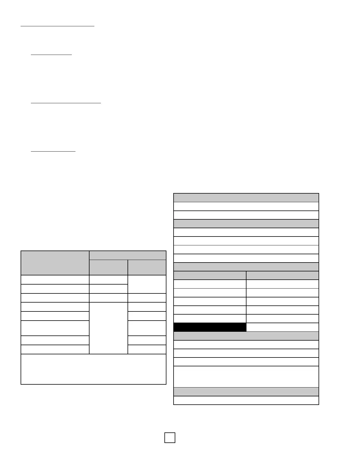
Recommended Flow Rates
Heat Pump
EAV040 – 12 GPM
EAV060 – 15 GPM
MPH Fan Coils/Air Handlers & ACH/MCH A-Coils
MPH/ACH/MCH024 – 6 GPM
MPH/ACH/MCH036 – 9 GPM
MPH/ACH/MCH048 – 13 GPM
MPH/ACH/MCH060 – 13 GPM
Mul-Aqua Fan Coils
High-wall units Console Units
MHQWW-9 – 3 GPM CFFWA-3 – 3 GPM
MHQWW-12 – 6 GPM CFFWA-6 – 4.5 GPM
MHQWW-18 – 6 GPM CFFWA-8 – 5.5 GPM
MHQWW-24 – 7 GPM CFFWA-12 – 8 GPM
MHQWW-36 – 10 GPM CFFWA-16 – 10.5 GPM
CFFWA-20 – 12.5 GPM
Radiant Floor
1/2" PEX – 0.5 to 0.75 GPM per circuit
5/8" PEX – 0.75 to 1 GPM per circuit
3/4" PEX - 1 to 1.25 GPM per circuit
Example: A 5 loop manifold with 1/2” PEX circuits would
need supply/return piping capable of supplying 2.5 to 3.75
GPM
DHW Piping
Use ow rate for heat pump
Pipe Diameter/Type
Maximum Flow Rate (GPM)
Floor Loop*
Supply/Re-
turn**
1/2” PEX 0.75
N/A
5/8” PEX 1
3/4” PEX 1.25 4
3/4” Copper or 1” PEX
N/A
7
1” Copper or 1-1/4” PEX 12
1-1/4” Copper or 1-1/2”
PEX
17
1-1/2” Copper 25
2” Copper 45
* Based upon 300 . circuits.
**Based upon 25. length (one-way) and 4 elbows
with water. When using anfreeze, increase pipe size
to the next size if close to the maximum ow rate.
Secon 5: Unit Piping