Enertech Global, LLC 55
AV : MD/ME - Rev. A Models
Installaon and Operaons Manual
• Check that the pipe system is complete.
• Check the pipe system for leaks.
• Check that the electrical installaon is prepared.
• Check that the electrical supply is connected so that the
compressor crankcase heater can start warming up the
compressor, if necessary.
• The compressor crankcase heater must have been acve
for at least 3 hours before compressor operaon can be
iniated. This is done by connecng control voltage. EAV
permits compressor start aer the compressor has been
warmed up. This can take up to 3 hours.
1. Fill the hydronic system to the necessary pressure.
2. Vent the system using the venng port on the ex tube
(included) and possibly the circulaon pump.
3. See “Flushing and Filling System” for details.
1. Communicaon cable, the EAV terminal block (X22:1-4)
must be connected.
2. Turn the isolator switch on.
3. Ensure that the EAV is connected to the power source.
4. Reinstall the removed panels and cover.
5. Aer the power to EAV has been switched on and there
is a compressor demand from the indoor module/control
module, the compressor starts once it has warmed up,
aer max 180 minutes. The length of this me delay
depends on whether the compressor has been warmed
up previously. See chapter Preparaons secon, above.
Preparing Piping System
Air is inially released from the water/anfreeze soluon and
venng may be necessary. If bubbling sounds can be heard
from the heat pump, the circulaon pump and piping/fan coils
the enre system will require further ushing/purging. When
the system is stable (correct pressure and all air eliminated)
the control system can be set as required.
General
EAV is equipped with an internal electronic controller that
handles all funcons necessary for operaon of the heat
pump, e.g. defrost cycle, stop at max/min. temperature,
connecon of the compressor heater, and protecve funcons
during operaon. Temperatures, number of starts and run
me, are displayed in the indoor module/control module.
The integrated control shows informaon via status-LEDs and
can be used during servicing.
Under normal operang condions the home owner does not
need to have access to the controller.
EAV communicates with the Enertech indoor module/control
module, which means that all sengs and measurement
values from EAV are adjusted and displayed on the indoor
module/control module.
Please wait.
Internal valve in Hot Water
Tank position.
3.10.1.2 3.10.1.3 3.10.1.4 3.10.1.5
3.10.1.6 3.10.1.7 3.10.1.8 3.10.1.9
3.10.1.10
3.9.0.3 3.9.1 3.10.0.1 Startup Wizard Button
3.10.1.1a
3.10.0.2 Startup Wizard Idle Prompt 3.10.1.1
This will take you back to
the startup wizard
Flush Outdoor Unit
Flush Outdoor Unit
heat exchanger and piping
between the Indoor/
Outdoor units until air is
removed.
Please open ALL zone
valves and press NEXT.
Please wait.
Internal valve in hydronic
position.
Completely flush every
circuit until it is void of all air.
Please open ALL zone
valves and press NEXT.
House zones test in
progress. Please wait:
5 min
House zones test in
progress. Please wait:
5 min
Step 1 Step 2 Step 3
The Startup Wizard is part of the First Run Setup. This Wizard
is designed to ensure that the system has the proper ow
rates and that air is purged from this system. Screens from the
Startup Wizard are shown on the following pages.
Secon 9: Equipment Start-Up
6. Adjust menu sengs via the indoor HMI (touchscreen
Human Machine Interface) as necessary.
7. Fill in the commissioning report.
8. Remove the protecve lm from the cover on EAV.
3.6.0 3.6.1 Hot Water Setpoint 3.6.2 Hot Water Deadband
3.7.2 Load Pump Max Speed 3.7.3 Delta Temp Heat Setpoint 3.7.4 Deta Temp Cool Setpoint
3.8.1 Pressure Units 3.8.2 Replace Filter 3.9.0
3.7.0 3.7.1 Load Pump Min Speed
3.7.5 Temp Units 3.8.0
3.9.0.1 3.9.0.2
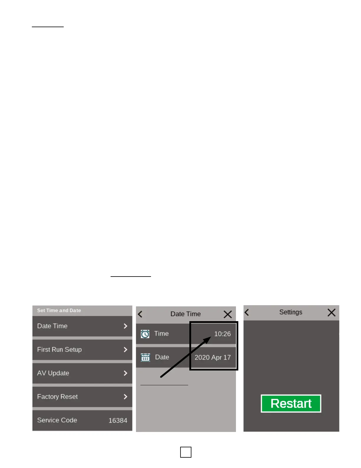
*MILITARY TIME*