Enertech Global, LLC 37
AV : MD/ME - Rev. A Models
Installaon and Operaons Manual
Optional connections
Communication
F2120 communicates with NIBE indoor modules/contr ol
modules by connecting a three core, screened cable (max
area 0.75 mm²) to terminal block X22:1– 4, as shown in
the following image.
For cascade connection, join terminal block X23 with
X22 to the next heat pump .
Softwar e version
In order for F2120 to be able to communicate with in-
door module (VVM ) / contr ol module (SMO ) the softwar e
version must be according to the table.
Softw ar e versionIndoor module /
Contr ol module
v7568R4VVM 310 / VVM 500
v7530R5VVM 320 / VVM 325
v7607R3SMO 20
v7635R5SMO 40
Disconnect the connections in F2120
PRESS
LEK
Push down!
1 2 3
29Chapter 5 | Electrical connectionsNIBE F2120
• EAV does not include a circuit breaker on the incoming
power supply. The heat pump’s supply cable must be
connected to a circuit breaker. A disconnect must be
installed near the unit per local code requirements.
• The roung of cables for heavy current and signals should
be made out through the cable openings on the heat
pump’s right-hand side, seen from the front.
• The communicaon cable must be a shielded cable and
be connected between EAV terminal block X22 and the
indoor module/control module
• Connect the ushing pump to the indoor module/control
module.
Note: Electrical installaon and wiring must be carried out in
accordance with local code by a qualied technician.
A power block is provided for incoming power to the EME/
EMD. This circuit supplies power to all of the controls, internal
pump, and immersion heater (if equipped).
Note: Reference the electrical data for circuit sizing.
Low Voltage
The EME/EMD eld wiring provides dry contact inputs to
interface directly with industry standard zone controllers and
aquastats. These are indicated with the following input pairs:
Heat: Radiant heang demand input
HHeat: Air handler heang demand input (120°F outlet
temperature)
Cool: Air handler cooling demand input (low temperature
water)
DHW: Domesc hot water thermistor (connect to thermistor
that is pre-installed in Turbomax tank)
OAT and OAT: These Terminals are Not Used, The outdoor
sensor is located in the Outdoor Unit, BT28 Sensor.
Secon 7: Field Wiring
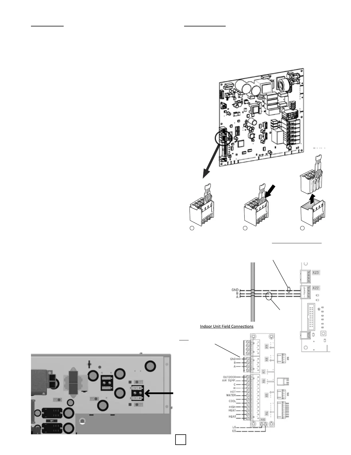
EAV communicates with Enertech indoor modules/control
modules by connecng a 3-conductor, shielded cable (max
area 0.75 mm²) to terminal block X22:1–4, as shown in the
following images.
Line Voltage
24
Enertech Global
AV/EM Models IOM
NOTE: USE THE UNINSULATED
CONDUCTOR FOR THIS CONNECTION.
Outdoor Unit Control Board
NOTE: USE THE 2 INSULATED
CONDUCTORS FOR A & B
Communica ons Wiring Between
Indoor and Outdoor Units
NOTE:
USE THE UNINSULATED
CONDUCTOR FOR GND
CONNECTION
24
Enertech Global
AV/EM Models IOM
NOTE: USE THE UNINSULATED
CONDUCTOR FOR THIS CONNECTION.
Outdoor Unit Control Board
NOTE: USE THE 2 INSULATED
CONDUCTORS FOR A & B
Communica ons Wiring Between
Indoor and Outdoor Units
NOTE:
USE THE UNINSULATED
CONDUCTOR FOR GND
CONNECTION