Enertech Global, LLC 29
AV : MD/ME - Rev. A Models
Installaon and Operaons Manual
Flush Cart Design
The Enertech Manufacturing ush cart has been designed to
eecvely and eciently ush the earth loop and to facilitate
injecng and mixing of the anfreeze.
Removing Debris During Flushing
Most ow center or pump failures are a result of poor water
quality or debris. Debris entering the loop during fusion and
installaon can cause noise and premature pump failure.
Enertech recommends a double ush ltering method during
purging. When purging, use a 100 micron bag lter unl air
bubbles are removed. Remove the 100 micron bag, replace it
with a 1 micron bag and restart the ushing.
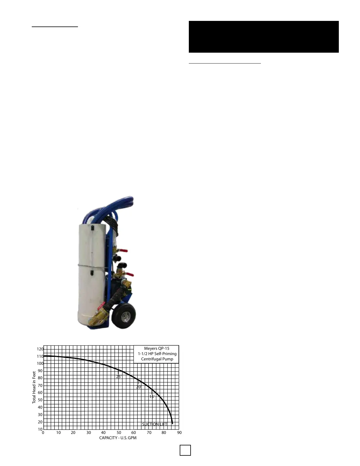
• Cylinder: HDPE, SDR15.5, 10” dia. (10 Gallons)
• Pump: Myers High Head QP15, 1.5hp, 115V
• Hose connecons: Cam Lock quick connects - 1-1/2”
hoses
• Hand Truck: 600lb rang with pneumac res
• Wiring: Liquid Tight metal on/o switch
• Tubing: SDR11 HDPE
• Connecons: 2 - 3/4” connecons for anfreeze and
discharge
• Drain: one on the pump and the tank
0 10 20 30 40 50 60 70 80 90
CAPACITY - U.S. GPM
120
110
100
90
80
70
60
50
40
30
20
10
Total Head in Feet
SUCTION LIFT
25’
20’
15’
Meyers QP-15
1-1/2 HP Self-Priming
Centrifugal Pump
Flush Cart Pump Curve:
Enertech Flush Cart:
Flushing and Filling System
The system needs to be ushed of air and debris, and lled
before it is turned on and put into service. All systems have
dirt and debris from the piping, soldering, etc. Enertech
recommends using a ush cart to the purge the system. The
ush cart should ulize a ½ HP pump, which is sucient for
almost all residenal hydronic systems, as long as each circuit
is isolated and ushed one at a me.
1. Isolate each circuit, including the heat pump and domesc
hot water tank.
2. Flush each zone of air, and ll each zone with water
(radiant tubing, air handler, etc.).
This step can be skipped if the unit is not equipped with hot
water capability.
1. Open the isolaon valves and ush/ ll the hot water tank
(if equipped), making sure to keep the system pressure
below 30 PSI.
Note: If the pressure gets above 30 PSI, the relief valve on
the tank will purge water.
2. Close the isolaons valves
Step 3: Heat Pump
1. Open the isolaon valves and ush/ ll the heat pump,
making sure that the water ow direcon is as it would be
in normal operaon.
Note: Water ow direcon is crucial during this step. If the
water ow is backwards, the Wye Strainer is not protecng
the braze plate heat exchangers from the miscellaneous
debris that hasn’t been ushed out into the ush cart.
2. Once the enre system has been ushed and lled, the
anfreeze and water treatment can be added, using the
ush cart to add and mix the treatment. All zones should
be open during this process, so that proper mixing can
take place.
3. Take mulple readings, and check the anfreeze
percentage, as the system is being mixed.
4. The nal step is to go through the set up wizard on the
controller (HMI) to energize the diverng valve (if
equipped) and verify that the last bit of air is removed
from the system.
5. Turn the 3-way valves on the ush valves back to the
normal operaon mode, which closes the ush port
connecons.
6. Open the ball valves on the ush cart to relieve pressure on
the hoses. Disconnect the hoses from the ush valves.
Note: If any small amount of air is sll in the system, the air
eliminaon device will remove it and the make-up water, as
well as the expansion tank, will keep pressure on the system.
Recommended pressure seng is 12-17 PSI cold = 15-19 PSI
hot.
The enre system is now ushed, lled, treated, and ready to
be put into operaon.
⚠ WARNING ⚠
MAKE SURE TO ISOLATE THE DOMESTIC WATER TANK
BECAUSE THE RELIEF VALVE INSTALLED IN THE TANK
WILL PURGE WATER AS THE SYSTEM IS FLUSHED.
Secon 5: Unit Piping