Enertech Global, LLC 23
AV : MD/ME - Rev. A Models
Installaon and Operaons Manual
It is important that the load side piping of the EAV system is
sized properly for the required ow rates and is ushed and
lled with good quality water and treatment. This will help
ensure that the longevity of the pump(s), braze plates, and
other load side components.
Piping Arrangement and Components
The Wye Strainer, which contains a #40 mesh, will collect
debris le in the piping aer the system has been ushed and
lled.
Per the installaon diagrams, boiler drains and isolaon valves
need to be integrated into the load piping for proper ushing
of the system at start up, as well as for future service. Full
port isolaon valves should be used in order to ensure low
pressure drop throughout the system.
Generally, the recommended load side piping arrangement
is designed as a parallel direct return system. Each zone is in
parallel and returns directly to the heat pump. Zone valves
should be ulized on each circuit to control the soluon ow
to each manifold/zone/circuit or distribuon device. Enertech
recommends zone valves have a CV rang of 8.9 or higher to
help guarantee proper ow and low pressure drop throughout
the system. All zone valves must be on/o style valves.
Note: If it is determined that any of the zone’s ow rates
are less than 5 GPM, a pressure dierenal bypass valve is
required for proper unit operaon (Enertech P/N: ADBV4A).
CAUTION
THIS SYSTEM UTILIZES A PRESSURIZED LOAD CIRCUIT. PLEASE ENSURE THE FOLLOWING:
1. The load side piping is flushed completely and purged of air (see Secon 6, Figures 7a to 7j).
2. The differenal bypass valve is installed, and in the correct orientaon (see page 16 and
drawing below).
3. The minimum pump speed is set to allow 5 GPM through the bypass valve
with all zones closed (see page 16) if hydraulic separator or buffer tank is not
used (a hydraulic separator or buffer tank is recommended).
NOTICE: A flush cart is required for purging air from the load side piping. See WV I.O.M.,
Figures 6a to 6c for valve arrangement and Secon 6 (Flushing and Filling) for flushing steps.
Remove this page from the manual before providing to building owner.
3. The minimum pump speed is set to allow 5 GPM through the bypass valve
with all zones closed (see page 16) if hydraulic separator or buffer tank is not
used (a hydraulic separator or buffer tank is recommended).
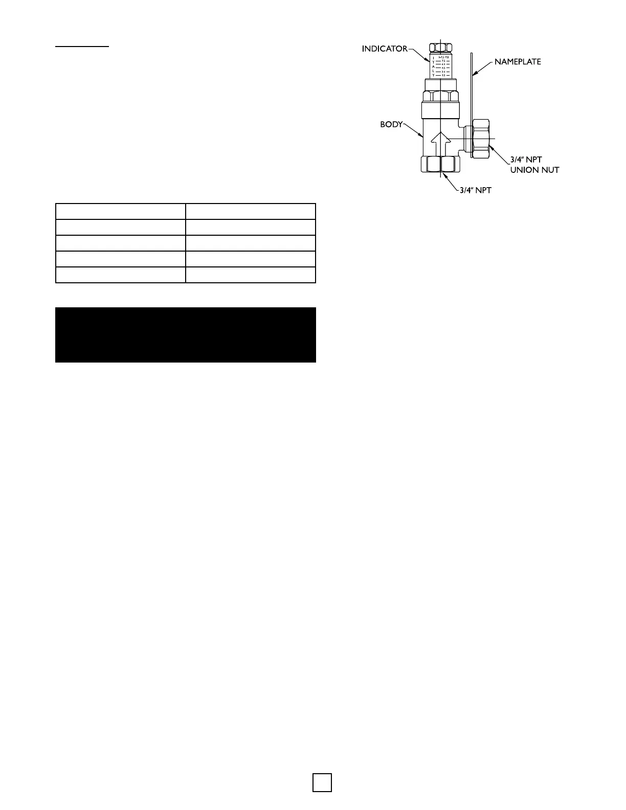
Bypass Valve
Follow the steps below for valve sengs.
1. The bypass valve seng should be adjusted during the
Startup Wizard when seng the minimum pump speed
(manual mode).
2. Set the adjustment indicator at 4.5 on the bypass valve.
3. In the Startup Wizard, start with the default minimum
pump speed at 60%. Open the zone valve for the smallest
zone (lowest ow rate). It will be important to know the
design ow rate for the smallest zone. For example, if the
smallest zone has 5 - 1/2” PEX circuits, the design ow
rate is typically 2.5 to 4 GPM. The combinaon of the
minimum pump speed and the bypass should provide a
minimum for 5 GPM.
4. Turn the adjustment indicator counter-clockwise to allow
the combined ow of the smallest zone and the bypass
valve to equal 5 GPM. The minimum pump speed may
need to be adjusted to higher than 60%, depending upon
the size of the zone.
Other Hydronic Components
An automac air eliminaon device and expansion tank are
factory installed in the indoor unit. They help remove any
micro-bubbles sll remaining aer purging and lling. The
expansion tank maintains minimum pressure in the hydronic
system for proper pump operaon.
Most local codes require certain components be installed
within the system. Local codes should be followed when
determining the exact requirements. A pressure relief valve
may be required, which should be rated for 30 PSI and
terminated 6” from the oor surface. Addionally, back-ow
preventer may be required and should be installed if a make-
up water line is connected from the water source to the load
side piping of the system.
Note: Even if a back-ow preventer is not required, it is
highly recommended.
⚠ NOTICE ⚠
THE EAV MONITORS FEEDBACK FROM THE CONNECTED
VARIABLE SPEED PUMP AND WILL NOT OPERATE
WITHOUT IT. A FLOW FAULT WILL OCCUR.
Load Piping
All interior piping must be sized for proper ow rates and
pressure loss. Insulaon should be used on all inside piping
when minimum temperatures are expected to be below
the dew point (less than approximately 50°F). Use the table
below for insulaon sizes with dierent pipe sizes. All pipe
insulaon should be made of closed cell and have a minimum
wall thickness of 3/8” for interior piping. Piping between the
Outdoor Unit and the Indoor Module should be at least 3/4”
wall thickness. All piping insulaon should be glued and sealed
to prevent condensaon and dripping. Interior piping may
consist of the following materials: PEX, copper, or stainless
steel hose (hose kit only). PVC and other piping types are not
recommended.
Secon 5: Unit Piping
Piping Material Insulaon Descripon
1” IPS Hose 1-3/8” ID - 3/8” Wall
1” IPS PE 1-1/4” ID - 3/8” Wall
1-1/4” IPS PE 1-5/8” ID - 3/8” Wall
2” IPS PD 2-1/8” ID - 3/8” Wall