Overview
1-4 Introduction
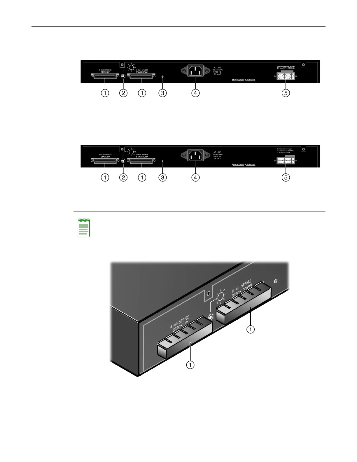
Figure 1‐5andFigu re 1‐6showthebackpanelsoftheB5switches.
Figure 1-5 B5 Switch Back Panels (Non-PoE B5 Switches)
Figure 1-6 B5 Switch Back Panels (PoE B5 Switches)
Figure 1-7 Stack Connection Port Cover
1 Stack connection ports (shown without covers) 4 AC power input connector
2 Rotary switch 5 Redundant power supply (RPS) connector
(shown without cover)
3 Password reset button
1 Stack connection ports (shown without covers) 4 AC power input connector
2 Rotary switch 5 Redundant power supply (RPS) connector
(shown without cover)
3 Password reset button
Note: By default, the stack connection ports are covered with removable covers. If you are not
connecting stacking cables, you must keep the covers on the stack connection ports to prevent EMI
leakage. If you remove the stacking cables, you must replace the cover on the stack connection
ports. See Figure 1-7.
1 Stack connection port covers

 Loading...


