Installing and Connecting B5 Redundant Power Systems
Enterasys B5 Gigabit Ethernet Switch Hardware Installation Guide 2-17
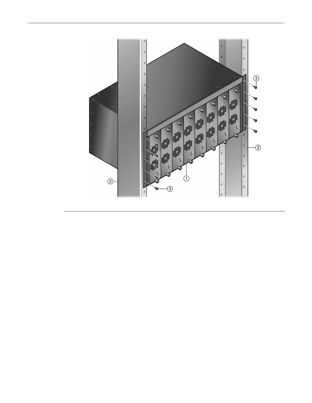
Figure 2-10 Fastening the STK-RPS-150CH8 to the Rack
Connecting the RPS Cable and ACPower Cord
TheredundantpowersupplyisconnectedtoaB5EthernetswitchswitchusinganRPScable.
Toconnectaredundantpowersupply,proceedasfollows:
1. UsingaPhilipsscrewdriver,removethecoverfromtheredundantpowersupplyconnector
ontheB5switch.
2. ConnectoneendoftheRPScabletothe
redundantpowersupplyconnectorontheB5switch.
Thenconnecttheotherendofthecabletotheredundantpowersupplyconnectorattherear
oftheRPSasshowninFigure 2‐11.
3. ConnecttheACpowercordtotheACinputpowerconnectorontheRPSshownin
Figure 2‐12
,thenplugtheACpowercordintothemainACpoweroutlet.
ThegreenPowerLEDonthefrontoftheRPSwillilluminatetoindicateasuccessful
connection.IftheLEDremainsoff,proceedasfollows:
a. ChecktheACpowercordconnectionattheACpowersourceandmake
surethepower
sourceiswithinspecification.
b. ChecktheACpowerconnectiontotheRPS.
c. Swapthe ACpowercordwithaknowngoodone.
d. IfthegreenLEDcontinuestoremainoff,contactEnterasys Networks.Referto“Getting
Help”onpage xviiforinstructions.Otherwise,proceedtostep4.
1 STK-RPS-150CH8 chassis 3 Mounting screws
2 Rails of 19-inch rack

 Loading...


