Installing the Switch on a Flat Surface
Enterasys B5 Gigabit Ethernet Switch Hardware Installation Guide 2-3
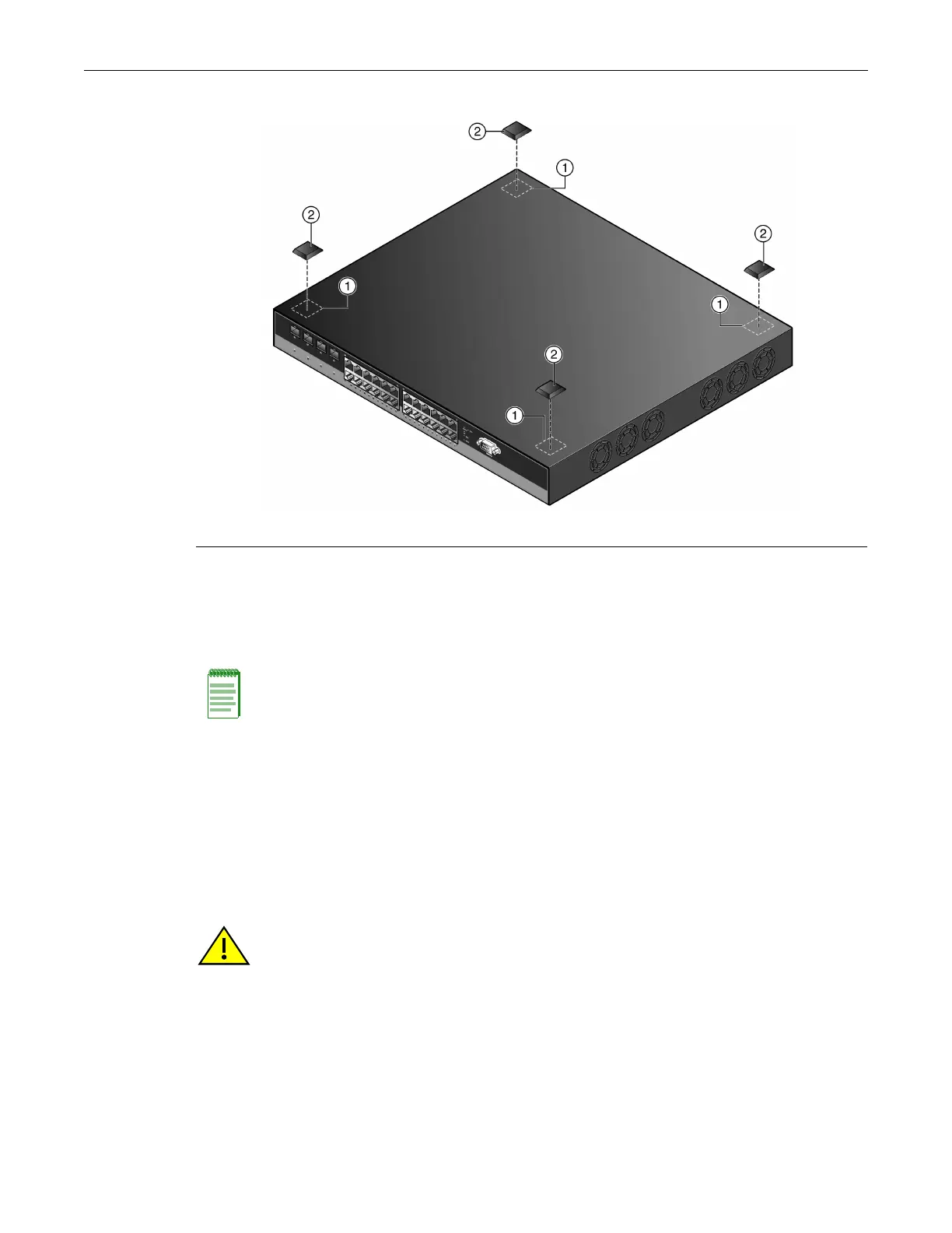
Figure 2-1 Chassis Bottom, Rubber Feet Placement
3. Removetheprotectivestripfromthebackofonerubberfootandpositionitonacornerand
pressfirmlyintoplace.
Repeatthisproceduretoinstalltheremainingthreerubberfeetintheotherthreecorners.
4. Afterinstallingtherubberfeet,returntheswitchtoitsuprightposition.
5. Proceedto“
GuidelinesforFlatSurfaceInstallation”onpage 2‐3.Forarackmountinstallation,
proceedto“RackMountingtheSwitch”onpage 2‐4.
Guidelines for Flat Surface Installation
Locatetheswitchwithin182.88cm(6ft)ofitspowersourceandonasurfaceasshownin
Figure 2‐2.Ifanoptionalredundantpowersystemisgoingtobeinstalledandconnectedtothe14‐
pinRedundantPowerSupplyinputconnectorontherearoftheswitch,
refertotheinstallation
guideshippedwiththeredundantpowersystem.
1 Locations to install the rubber feet (four locations) 2 Rubber feet with adhesive backing (four)
Note: If a number of switches are being installed in a stack, repeat steps 1 through 4 to install the
rubber feet on each switch before continuing with the installation.
Caution: To ensure proper ventilation and prevent overheating, leave a minimum clearance space
of 5.1 cm (2.0 in.) at the left and right of the switch.
Do not connect the switch to the AC power source until instructed to do so later in the installation
process.
Precaución: Para asegurar una buena ventilación y evitar que el sistema se sobrecaliente, deje un
espacio mínimo de 5.1 cm (2 pulgadas) con respecto a los lados y a la parte posterior del aparato.
No conecte el dipositivo a la fuente primaria hasta que no se le indique.

 Loading...


