RPS Specifications
Enterasys B5 Gigabit Ethernet Switch Hardware Installation Guide A-7
STK-RPS-150PS Redundant Power Supply Connector
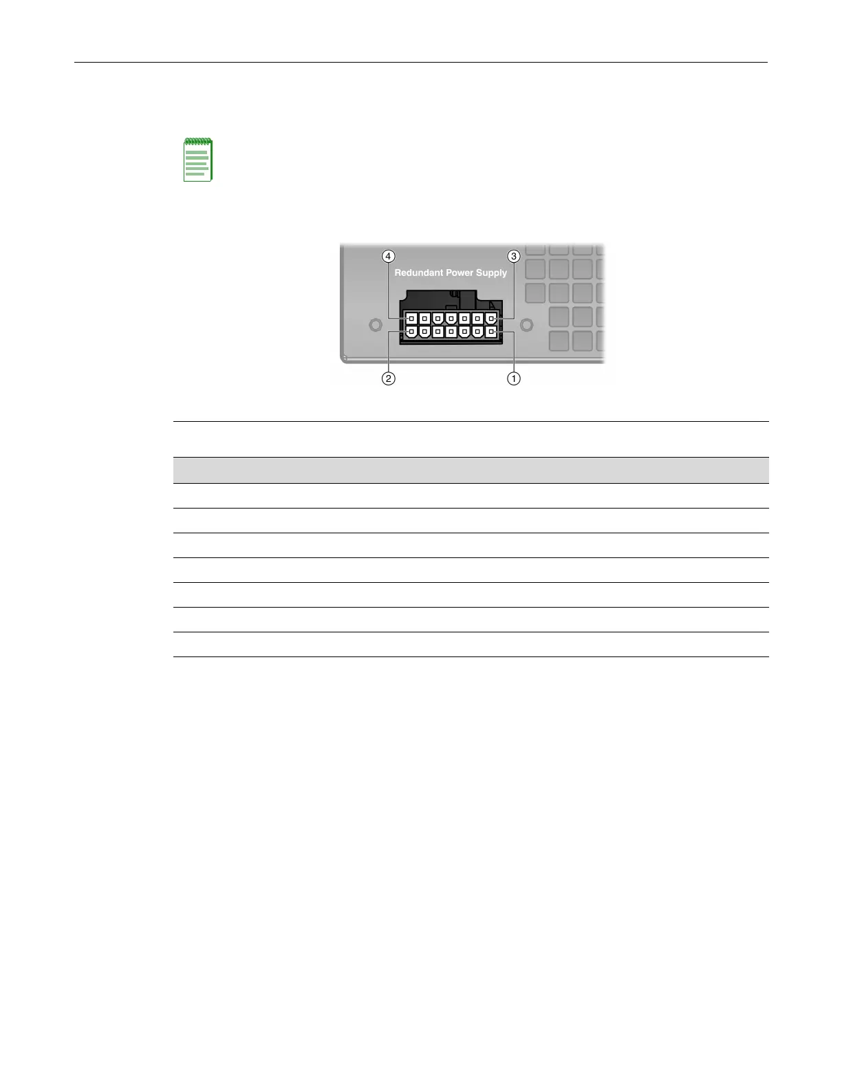
Forpinlocationandfunction,refertoFigure A‐1andTable A‐6,respectively.
Figure A-1 STK-RPS-150PS Redundant Power Supply Connector Pin Locations
Note: The following information is for troubleshooting purposes only. For proper operation, do not
use any other cable except the RPS cable supplied with the STK-RPS-150PS. This cable is
specially designed for this application and meets all necessary regulatory and safety standards.
The use of non-approved cables will void your warranty.
1 Pin 1 2 Pin 7 3 Pin 8 4 Pin 14
Table A-6 STK-RPS-150CH2 Redundant Power Supply Connector Pin Functions
Pin Number Function Pin Number Function
1 Ground 8 Ground
2 No connection 9 No connection
3 12 Vdc Output 10 No connection
4 12 Vdc Output 11 Status 1
5 12 Vdc Output 12 Status 2
6 12 Vdc Output 13 Power good
7 Ground 14 Ground

 Loading...


