Installing and Connecting B5 Redundant Power Systems
Enterasys B5 Gigabit Ethernet Switch Hardware Installation Guide 2-21
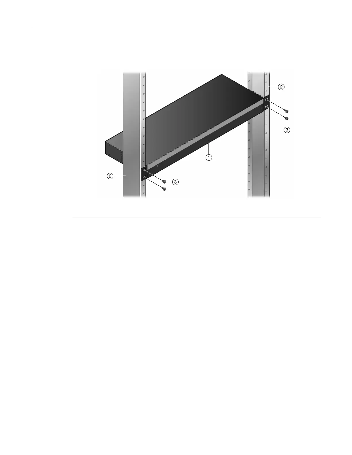
2. Withthemountingbracketsattached,positiontheSTK‐RPS‐500PSbetweentheverticalframe
membersofthe19‐inchrackasshowninFigure 2‐15.ThenfastentheSTK‐RPS‐500PSsecurely
totheframeusingfourcustomer‐suppliedrackscrews.
Figure 2-15 Fastening the STK-RPS-500PS to the Rack
3. Ifyouare installingtheSTK‐RPS‐500PSin
astackedconfiguration,repeatthisprocedurefor
eachSTK‐RPS‐500PS,thenproceedtoConnectingtheRPSCableandACPowerCord.
Installing the STK-RPS-500PS on a Flat Surface
WheninstallingtheSTK‐RPS‐500PSonaflatsurface,theinstallationoftherubberfeetis
recommendedtopreventtheSTK‐RPS‐500PSfromslidingonaflatsurface.
Toinstalltherubberfeet:
1. PlacetheSTK‐RPS‐500PSonitsbackonasturdyflatsurfacetogainaccessto
thebottomofthe
chassis.
2. Removethefourrubberfeetfromtheirplasticbagintheshippingbox.
3. Locatethefourmarkedlocationsonthebottomfour cornersoftheSTK‐RPS‐500PS.
4. Removetheprotectivestripfromthebackofonerubberfootandpositionitonamarked
location
andpressfirmlyintoplace.Repeatthisproceduretoinstalltheremainingthree
rubberfeet.
5. Afterinstallingtherubberfeet,returntheSTK‐RPS‐500PStoitsuprightposition.
Connecting the RPS Cable and ACPower Cord
TheSTK‐RPS‐500PSisconnectedtotheB5PoEswitchusingtheRPScable,asfollows:
1. TurnofftheB5switchandunplugitfromthepowersourcebeforeinstallingtheSTK‐RPS‐
500PS.
TheB5switchdoesnotsupporthotinsertion/removalofanRPScable.Ifyouhotinsert
anRPS
cableintoarunningB5switch,theB5switchwillnotrecognizethatanRPScableisinstalled
andtheB5switchwilllosepoweriftheprimarypowersupplyfails.
1 STK-RPS-500PS 3 Mounting screws
2 Rails of 19-inch rack

 Loading...


