Checking the LEDs
Enterasys B5 Gigabit Ethernet Switch Hardware Installation Guide 3-3
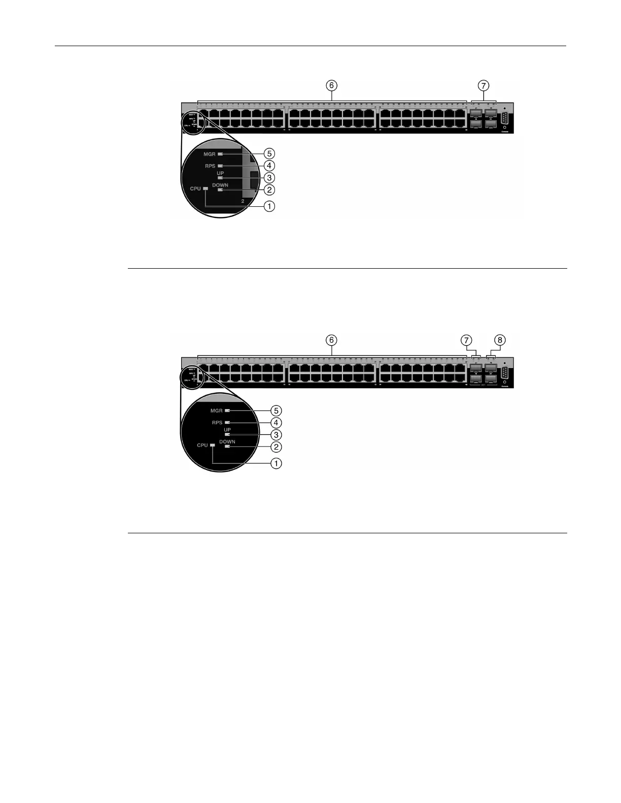
Figure 3-3 B5G124-48 and B5G124-48P2 LEDs
Figure 3-4 B5K125-48 and B5K125-48P2 LEDs
1 CPU LED 5 MGR LED
2 STACK DOWN LED 6 Link/Activity/PoE LEDs for 10/100/1000 Mbps
RJ45 ports 1 through 483 STACK UP LED
4 RPS LED for redundant power source status 7 Link/Activity LEDs for SFP ports 47 through 50
1
1. These SFP ports will only establish a link when the RJ45 port equivalent is not linked. (For example, when
SFP port 47 is linked, RJ45 port 47 is deactivated. When the SFP is not linked, the RJ45 port 47 is reactivated
and can establish a link as long as the SFP port 47 is not linked first.)
1 CPU LED 6 Link/Activity/PoE LEDs for 10/100/1000 Mbps
RJ45 ports 1 through 482 STACK DOWN LED
3 STACK UP LED 7 Link/Activity LEDs for SFP ports 47 and 48
1
1. These SFP ports will only establish a link when the RJ45 port equivalent is not linked. (For example, when
SFP port 47 is linked, RJ45 port 47 is deactivated. When the SFP is not linked, the RJ45 port 47 is reactivated
and can establish a link as long as the SFP port 47 is not linked first.)
4 RPS LED for redundant power source status 8 Link/Activity LEDs for 10G ports 49 and 50
5 MGR LED

 Loading...


