Completing the Installation
2-30 Installation
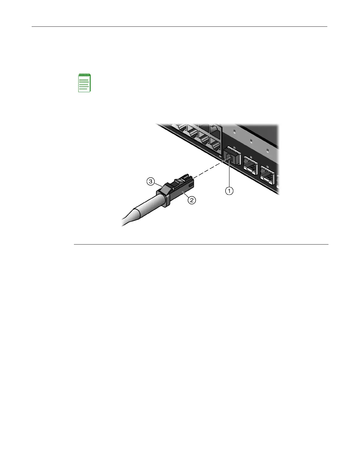
RefertoFigure 2‐20asyouperformthefollowingprocedure.
ToconnectanLCorMT‐RJcableconnectortoanSFPor10Gportconnector:
1. Removetheprotectivecovers(notshown)fromtheuplinkportSFP/10Gandfromthe
connectorsoneachendofthecable.
2. Insertthecableconnectorinto
theSFP/10Gconnectoruntilitclicksintoplace.
Figure 2-20 Cable Connection (LC shown) to Uplink Port with SFP/10G Installed
3. Plugtheotherendofthecableintotheappropriateportontheotherdevice.Somecablesmay
beterminatedattheotherendwithtwoseparateconnectors,oneforeachfiber‐opticstrand.
Inthiscase,ensurethatthetransmitfiber‐opticstrand
fromtheB5switchisconnectedtothe
receiveportoftheotherdevice,andthereceivefiber‐opticstrandontheB5switchis
connectedtothetransmitportoftheotherdevice.
4. RepeatthisprocedureforotherSFP/10Gports,ifneeded.
5. IfanSFP/10Gportisunused,installadust
cover.
Completing the Installation
Afterinstallingtheswitchandmakingtheconnectionstothenetwork,accesstheswitch
management,asdescribedbelow.
Initial Logon to Switch Management
ToinitiallyaccessswitchmanagementfromyourlocalPC,terminal,ormodemconnection,
proceedasfollowsatthedisplayedstartupscreen:
1. Enterrw(Read‐Write)forUsername.
2. AtthePasswordprompt,pressEnter(RETURN).
Note: Leave the protective covers in place when the connectors are not in use to prevent
contamination.
1 Combo SFP port with transceiver installed 2 LC cable connector 3 Release tab

 Loading...


