Connecting to the Console Port for Local Management
2-22 Installation
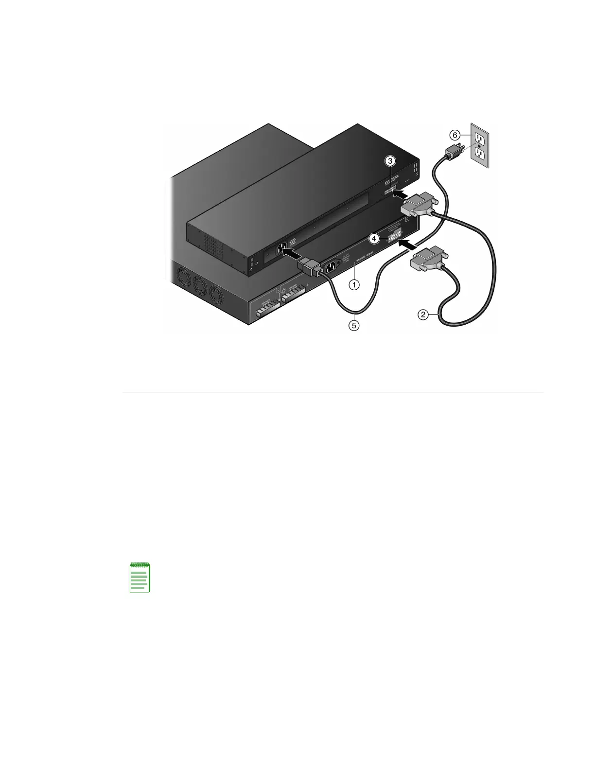
2. ConnectoneendoftheRPScabletotheredundantpowersupplyconnectorontheB5switch.
ThenconnecttheotherendtotheredundantpowersupplyconnectorattherearoftheSTK‐
RPS‐500PSasshowninFigure 2‐16.
Figure 2-16 STK-RPS-500PS RPS Cable and AC Power Cord Connections
3. ConnectastandardACpowercordtotheAC
inputpowerconnectorontheSTK‐RPS‐500PS,
thenplugtheACpowercordintothemainACpoweroutletasshowninFigure 2‐16.
TheACpowerLEDonthefrontoftheSTK‐RPS‐500PSwillturngreentoindicateasuccessful
connectionandtheSTK‐RPS‐500PSis
operatingproperly.
4. ReconnecttheB5switchtotheACpowersource.
5. TurnontheB5switch.
Connecting to the Console Port for Local Management
ThissectiondescribeshowtoinstallanRS232DTEinterfacecabletoaPC,aVTseriesterminal,or
amodemtoaB5forout‐of‐bandsessionsusingCLIcommands.
1 B5 switch 5 AC power cord (type varies depending on country)
2 RPScable 6 AC power outlet with ground connection (type
varies depending on country)
3 STK-RPS-500PS output connector
4 B5 redundant power supply connector
Note: When switches are connected in a stack configuration and all high-speed stacking cables are
connected before powering up the switches, one switch in the stack will be automatically
designated as the Manager of the stack and its Console port will remain active. All other switches
will become Member switches and their Console ports will be deactivated.

 Loading...


