Installing and Connecting B5 Redundant Power Systems
Enterasys B5 Gigabit Ethernet Switch Hardware Installation Guide 2-11
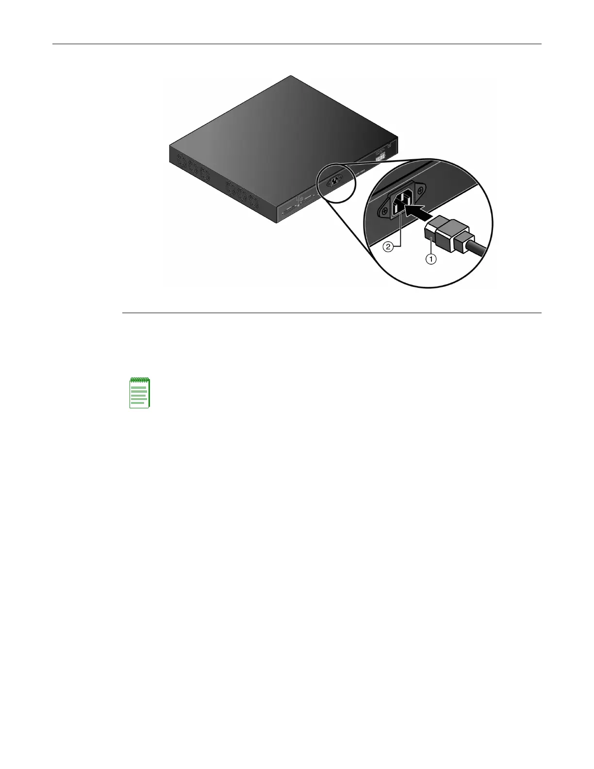
Figure 2-6 Switch Rear View
3. ObservethatthepowerCPULED(notshown),locatedonthefrontpanel.Duringthe
initialization,theCPULEDwillstartbyilluminatingsolidamber,thenstartblinkinggreen,
thenblinkingamber,thenblinkinggreenagainuntiltheendoftheinitialization,andthen
turnssolidgreen.
Iftheswitch
isastandaloneswitch,itwilltakeapproximately30 secondsfortheswitchto
startup.Ifthesw itchisastackmanager,itcantakeupto3minutesormoretostartup,
dependingonthenumberofmemberswitchesinthestack.
Installing and Connecting B5 Redundant Power Systems
DependingonyourB5switch,youcaninstalloneofthefollowingredundantpowersupplies:
•STK‐RPS‐150PS,a150Wredundantpowersupplyfornon‐PoEB5models.
•STK‐RPS‐500PS,a500WredundantpowersupplyforPoE‐compliantB5models.
STK-RPS-150PS
YoucaninstallanSTK‐RPS‐150PSinthefollowingRPSshelves:
•STK‐RPS‐150CH2,atwo‐slotchassis
•STK‐RPS‐150CH8,aneight‐slotchassis
Required Tools
Aflat‐bladescrewdriverisrequiredtoinstalltheSTK‐RPS‐150CH2 orSTK‐RPS‐150CH8shelfand
STK‐RPS‐150PSpowersupplies.
1 AC power cord 2 AC power connector
Note: If the CPU LED illuminates solid red, there was a critical failure. For more information about
the LED indications and troubleshooting, refer to Chapter 3, Troubleshooting. If you need
additional help, contact Enterasys Networks. Refer to “Getting Help” on page xvii for details
.

 Loading...


