Connecting to the Console Port for Local Management
Enterasys B5 Gigabit Ethernet Switch Hardware Installation Guide 2-23
What Is Needed
ThefollowingisalistofinterfacecablesthatmaybeneededtoconnecttheDB9maleConsoleport
connectorontheswitch.ThecablesareterminatedbyaDB9femaleconnectoratoneend,andby
oneofthreetypeconnectorsattheotherend,dependingonthetypeconnection
neededforthe
remotedevice.Thecablesthatmaybeneededareasfollows:
•DB9female‐to‐DB9female(suppliedwithswitch)
•DB9female‐to‐DB25female
•DB9female‐to‐DB25male
UsingaDTEmodemDB9female‐to‐DB9femalecable,youcanconnectproductsequippedwitha
DB9DTEmale
consoleporttoanIBMorcompatiblePCrunningaVTseriesemulationsoftware
package.
UsingaDTEmodemDB9female‐to‐DB25femalecable,youcanconnectproductsequippedwith
aDB9DTEmaleconsoleporttoaVTseriesterminalorVTtypeterminalsrunningemulation
programsforthe
VTseries.
UsingaDTEmodemDB9female‐to‐DB25malecable,youcanconnectproductsequippedwitha
DB9DTEmaleconsoleporttoaHayescompatiblemodemthatsupports9600 baud.
ThecableusedmustconnecttheConsoleportReceivedData,Pin2totheTransmittedDatapinat
the
otherendofthecable.TheconnectionfromtheConsoleportTransmittedData,Pin3(mustbe
connected)totheReceivedDatapincableconnectionattheotherendofthecable.TheDB9
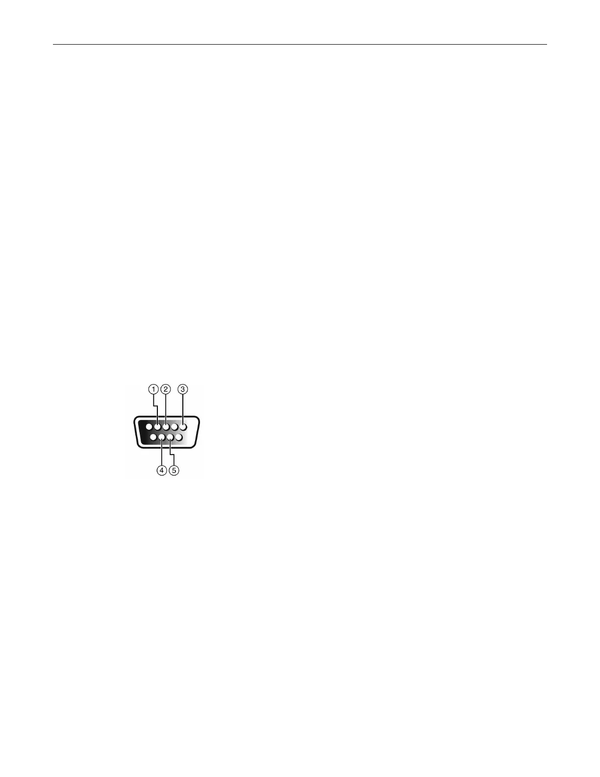
ConsoleportpinassignmentsareshowninFigure 2‐17.
Figure 2-17 DB9 Male Console Port Pinout Assignments
1 Pin 2, Received Data (input)
2 Pin 3, Transmitted Data (output)
3 Pin 5, Signal Ground
4 Pin 7, Request to Send
5 Pin 8, Clear to Send
All other pins not connected.

 Loading...


