Checking the LEDs
3-2 Troubleshooting
Checking the LEDs
ThefollowingsectionsdefinethebehavioroftheLEDsontheB5chassismodels.Referto
Figure 3‐1,Figure 3‐2,Figure 3‐3,andFigure 3‐4forthelocationoftheLEDsonthechassis.
Figure 3-1 B5G124-24 and B5G124-24P2 LEDs
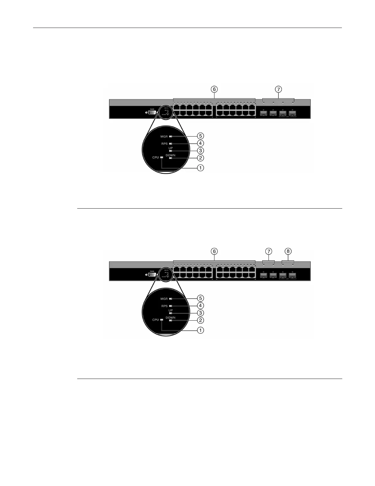
Figure 3-2 B5K125-24 and B5K125-24P2 LEDs
1 CPU LED 5 MGR LED
2 STACK DOWN LED 6 Link/Activity/PoE LEDs for 10/100/1000 Mbps for
RJ45 ports 1 through 243 STACK UP LED
4 RPS LED for redundant power-source status 7 Link/Activity LEDs for SFP ports 23 through 26
1
1. SFP ports 23 and 24 will only establish a link when the RJ45 port equivalent is not linked. (For example, when
SFP port 23 is linked, RJ45 port 23 is deactivated. When the SFP is not linked, the RJ45 port 23 is reactivated
and can establish a link as long as the SFP port 23 is not linked first.)
1 CPU LED 6 Link/Activity/PoE LEDs for 10/100/1000 Mbps for
RJ45 ports 1 through 242 STACK DOWN LED
3 STACK UP LED 7 Link/Activity LEDs for SFP ports 23 and 24
1
1. These SFP ports will only establish a link when the RJ45 port equivalent is not linked. (For example, when
SFP port 23 is linked, RJ45 port 23 is deactivated. When the SFP is not linked, the RJ45 port 23 is reactivated
and can establish a link as long as the SFP port 23 is not linked first.)
4 RPS LED for redundant power-source status 8 Link/Activity LEDs for 10G ports 25 and 26
5 MGR LED

 Loading...


