Enterasys I-Series Hardware Installation Guide 1-1
1
Introduction
The Enterasys I-Series switch is an industrially-hardened Ethernet switch especially designed to
handle networking in physically demanding environments like manufacturing plants, oil
refineries, and utilities.
Overview
The I-Series switch supports up to 24 IEEE 802.3U Fast Ethernet ports and two IEEE 802.3Z
Gigabit Ethernet ports. The I-Series switch can be placed as a freestanding unit, installed into a
standard 48.26-centimeter (19-inch) rack, or mounted to an industry-standard DIN rail. The top of
the switch is a heat sink so that the I-Series switch can operate in an industrialized environment
without special cooling requirements.
All cable connectors, power and relay connectors, and LED indicators are located at the front of
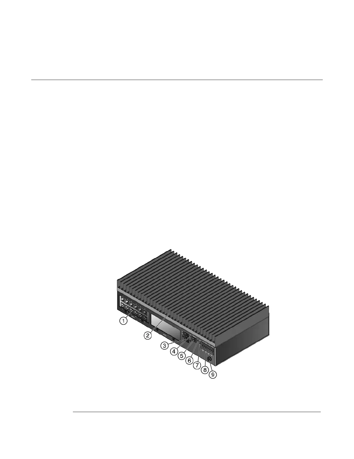
the switch, as shown in Figure 1-1.
Figure 1-1 I-Series Switch with One IOM
1 IOM 4 CPU LED 7 Power LEDs
2 Heat sink 5 Console port 8 Power and relay connectors
3 Uplink connectors and LEDs 6 Reset button 9 Ground connector
 Loading...