Replacing the IOM in Slot 1
3-8 Troubleshooting
4. Inside the switch, locate and remove the two screws at the back of the IOM. Do not let the
screws damage the inside of the switch. Save the screws.
5. Remove the two screws from the front of the chassis that hold the IOM in place. Note that a
cable retention bracket may also be attached by the two screws. Save the two screws, and the
retention bracket, if applicable.
6. Gently lift the IOM. There may be some resistance.
7. Push in the IOM at the bottom (closest to the surface where the switch is resting).
8. If the sticky heat pad is removed with the IOM, replace the heat pad on the block.
9. Put the IOM aside.
10. Place your hand on the switch as you unpack the replacement IOM to prevent electrostatic
discharge.
11. If the replacement IOM has a cable retention bracket attached, remove the bracket and save
the two screws.
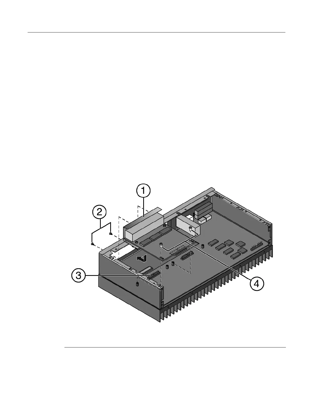
12. Hold the IOM above the access opening with the printed circuit side facing up as shown in
Figure 3-6. Then slide the front of the IOM into the enclosure so that the front of the IOM fits
into the front panel opening.
Figure 3-6 Installing the IOM
1 IOM 3 Sockets
2 Front panel screws 4 Post screws
 Loading...