Completing the Installation
2-36 Installation
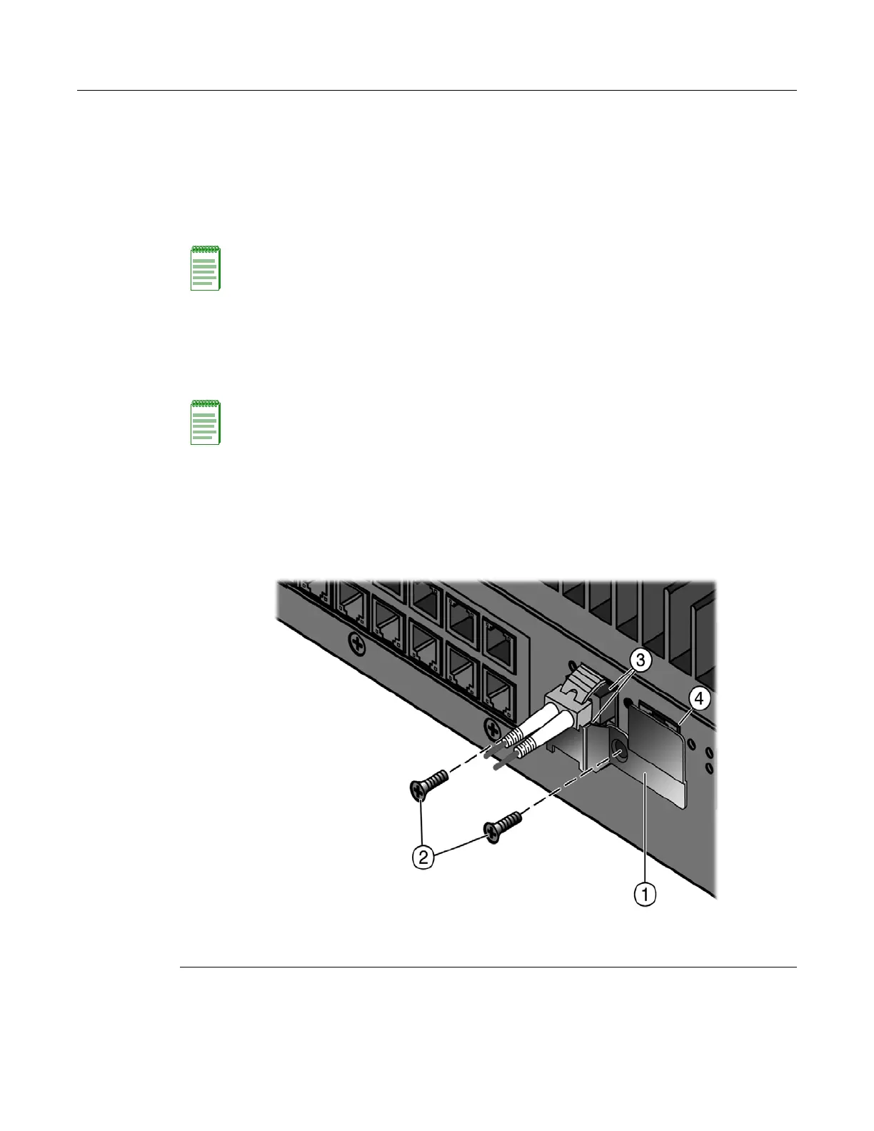
Securing the Uplink Cables
To secure the I-Series switch uplink cables for operation in a hazardous environment, refer to
Figure 2-26 and perform the following:
1. Remove the console cable.
2. Locate the appropriate retention bracket and two screws.
3. Place the appropriate bracket over the uplink connector(s) as shown in Figure 2-26. Make sure
the cables are held firmly in place and that the tab on the bracket covers the console port.
4. Fasten the bracket with the two screws.
If you require assistance, contact Enterasys Networks using one of the methods described in
“Getting Help” on page xvi.
Figure 2-26 Securing an Uplink Port Cable (fiber Mini-GBIC industrial bracket shown)
Note: The bracket for use with fiber industrial grade Mini-GBICs (I-MGBIC-GSX, I-MGBIC-GZX and
I-MGBIC-GLX) is installed on the uplink ports at the time of shipment. The bracket for use with
copper industrial grade Mini-GBICs (I-MGBIC-GTX) is not installed at the time of shipment and is
packaged separately.
Note: You must install the appropriate retention bracket if the I-Series switch will be installed in a
Class 1, Division 2 hazardous environment. Brackets are designed for use with industrial grade
Mini-GBICs (I-MGBIC-xxx) only.
The bracket is not required for use in non-hazardous environments and will not fit over standard
Mini-GBICs.
1 Bracket 3 Uplink connector
2 Screws for bracket 4 Console port tab
 Loading...