Checking the LEDs
Enterasys I-Series Hardware Installation Guide 3-3
The two power LEDs, marked PRI and SEC, indicate voltage for the primary and secondary
power inputs. Table 3-3 describes their status.
IOM Port LEDs
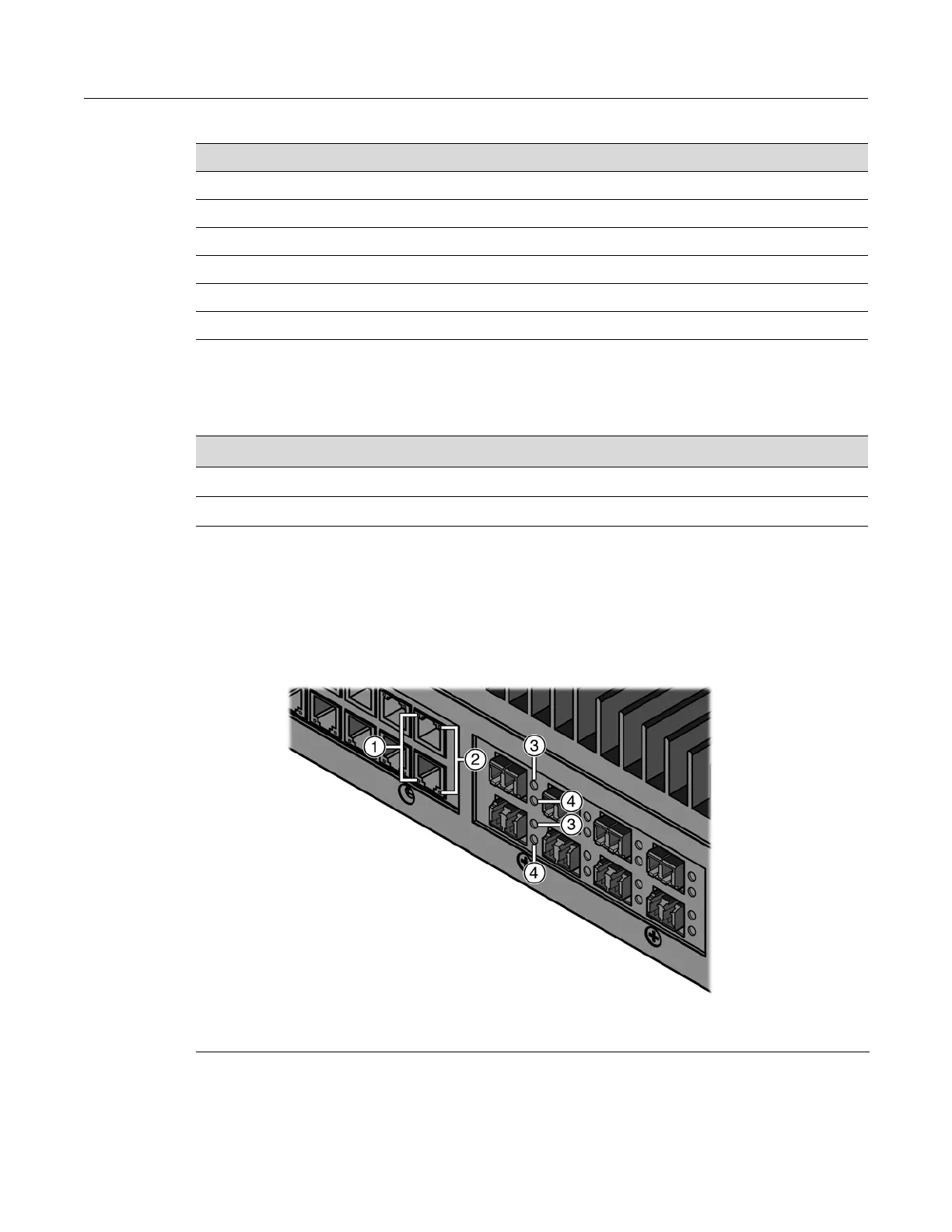
Refer to Figure 3-2 and Table 3-4 for the location and definition of the port LEDs on the I-Series
switch IOMs.
Figure 3-2 IOM LEDs
Table 3-2 CPU LED Definitions
Display Status
Solid red Major system failure, including failure to boot.
Blinking red Manufacturing test failed.
Solid amber Diagnostics are running.
Blinking amber Functional image is loaded.
Solid green System is fully operational.
Blinking green System is booting.
Table 3-3 Power LED Definitions
Display Status
Off No power, or voltage has dropped below 18 V.
On Power is applied.
1 Activity LED on RJ45 connectors 3 Activity LED on fiber connectors
2 Link LED on RJ45 connectors 4 Link LED on fiber connectors
 Loading...