Mounting the Switch
2-18 Installation
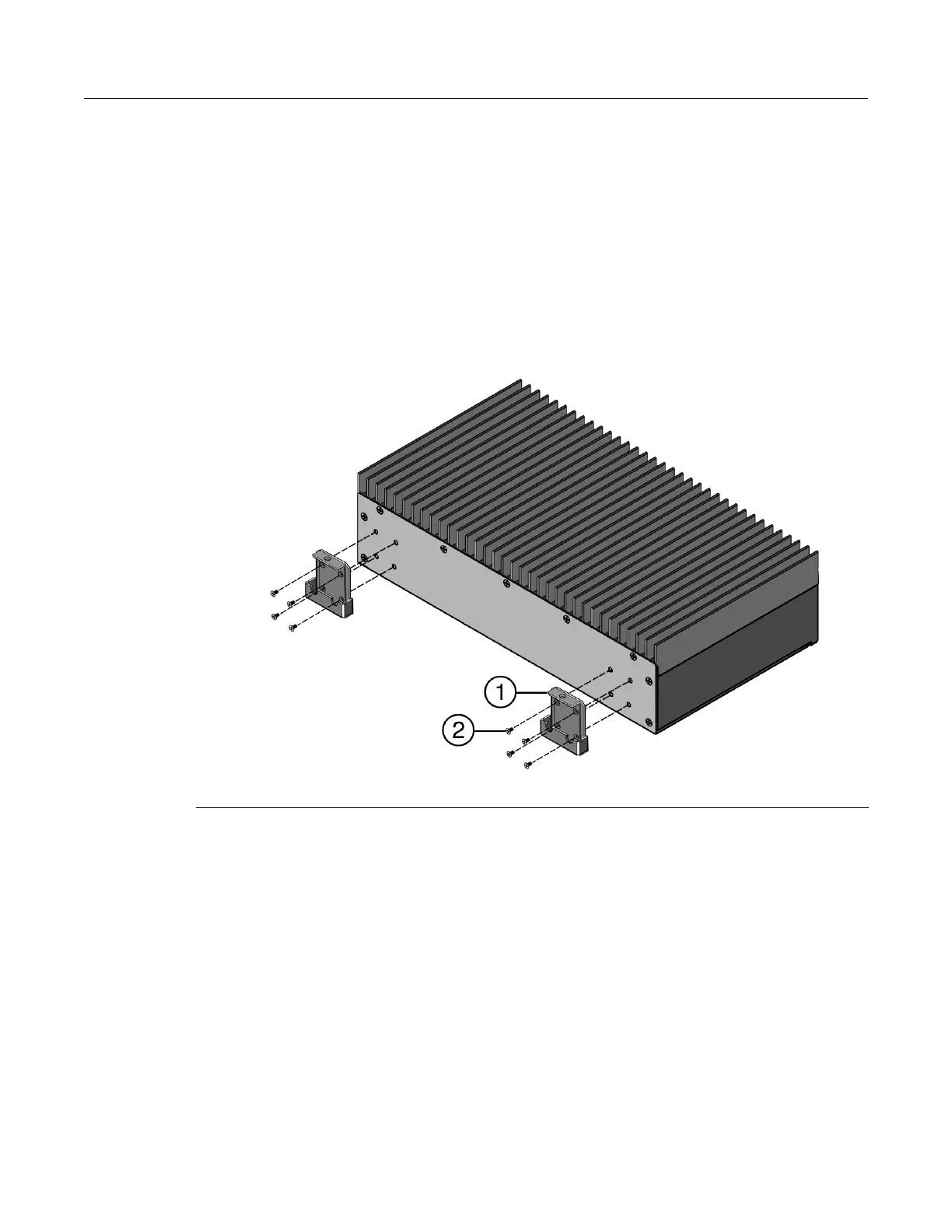
4. If installing the DIN clip to the back of the switch, you must install both DIN clips. Refer to
Figure 2-14 on page 2-18 and perform the following:
a. Locate the 4 screws in the back of the switch at each side, as shown in Figure 2-14, and
remove the screws. Save the screws.
b. Determine how the clips need to attach to the back of the switch. It is recommended that
the base rail clips attach to the top of a horizontally-mounted DIN rail, but they can attach
to the left or right side of a vertically-mounted DIN rail.
c. Attach one DIN clip using four screws.
d. Attach the other DIN clip using the remaining four screws.
Figure 2-14 Installing DIN Clips to the Back of the Switch
5. Refer to Figure 2-15 on page 2-19 and hook the notches on the base rail clip onto one side of
the rail itself. If attaching to a horizontal DIN rail, make sure that the base rail clip is on top.
6. Secure the latch to the clip, making sure that the notches in the latch attach to the other rail.
7. Tighten the captive screw.
8. Make sure that the switch is securely fastened to the rail.
1 DIN clip 2 Screws
 Loading...