Completing the Installation
Enterasys I-Series Hardware Installation Guide 2-35
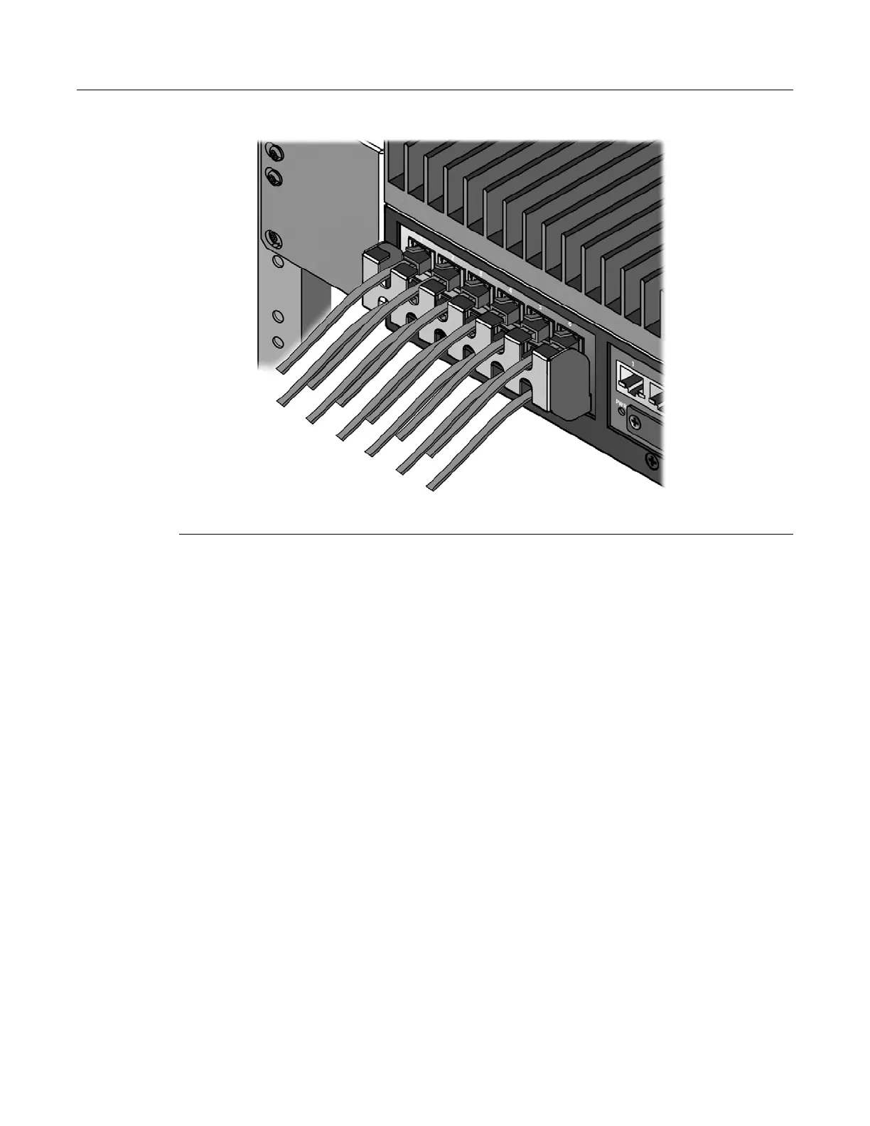
Figure 2-25 Securing the IOM Connector Cables
Completing the Installation
1. Power on the switch.
2. Verify that the Power LEDs are lit.
3. Verify that the CPU LED blinks initially then becomes solid green.
4. Make sure that the network devices connected to the uplink ports are powered on, then verify
that each Link/Activity LED is ON (solid green or blinking green).
5. Make sure that the network devices connected to the IOM ports are powered on, then verify
that each Link LED is ON (solid green).
6. At the device connected to the console port, perform the following:
a. Enter admin for Username.
b. At the Password prompt, press ENTER (RETURN).
c. For details on how to configure the I-Series using the command line interface, refer to the
Enterasys I-Series CLI Reference Guide. The CLI commands enable you to set a new
password, configure the relays, and perform more involved management configurations
on the I-Series.
7. If the I-Series switch is installed in a hazardous environment, after you are confident that the
installation is successful, you must install the retention bracket to secure the uplink
connections and cover the console port as described in the following section.
1 IOM 2 Bracket 3 Screws
 Loading...