Checking the LEDs
3-2 Troubleshooting
Checking the LEDs
The following sections define the behavior of the LEDs on the I-Series switch chassis and on the
IOMs. Refer to Figure 3-1 for the location of the LEDs on the chassis and to Figure 3-2 for the
location of the LEDs on the IOMs.
I-Series Switch Chassis LEDs
Refer to Table 3-1, Table 3-2, and Table 3-3 for definitions of the LEDs on the I-Series switch
chassis.
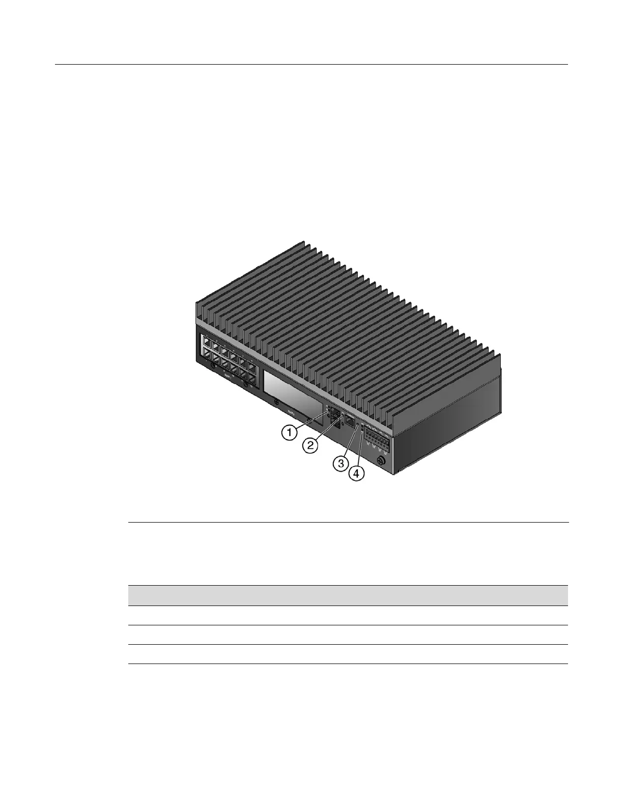
Figure 3-1 I-Series Switch Chassis LEDs
The uplink port LEDs on the front panel, marked 25 for the top port and 26 for the bottom port,
indicate link activity. Their status is described in Table 3-1.
The CPU LED indicates the state of the system, as described in Table 3-2.
1 Uplink port LEDs 3 Reset button
2 CPU LED 4 Power LEDs
Table 3-1 Uplink Port LED Definitions
Display Status
Off No activity.
Blinking green Activity over link.
Solid green Link established.
 Loading...