Figures xi
Figure Page
Figures
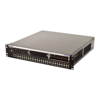
1-1 Matrix E1 1G694-13 Standalone Switch .........................................................................1-1
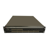
1-2 Optional Ethernet Expansion Modules ............................................................................1-3
3-1 Removing the Front Panel Coverplate ............................................................................3-3
3-2 Installing the Ethernet Expansion Module .......................................................................3-4
3-3 Mini-GBIC Installation...................................................................................................... 3-6
3-4 XENPAK Module Installation...........................................................................................3-8
3-5 Clearance Required for Tabletop or Shelf Installation..................................................... 3-9
3-6 Attaching the Rackmount Brackets ............................................................................... 3-11
3-7 Fastening the Switch to the Rack.................................................................................. 3-11
3-8 AC Power Connections .................................................................................................3-12
3-9 Cable Connection to Mini-GBIC ....................................................................................3-14
3-10 SC Fiber Optic Cable Connection .................................................................................3-17
3-11 Connecting an IBM PC or Compatible ..........................................................................3-19
3-12 Connecting a VT Series Terminal .................................................................................3-21
3-13 Connecting to a Modem ................................................................................................3-22
4-1 LANVIEW LEDs ..............................................................................................................4-2
4-2 Reset Switch ...................................................................................................................4-7
B-1 Removing the Chassis Cover ......................................................................................... B-3
B-2 Mode Switch Location (Chassis, Top View) ................................................................... B-4

 Loading...


