Connecting to Console Port for Local Management
Hardware Installation 3-23
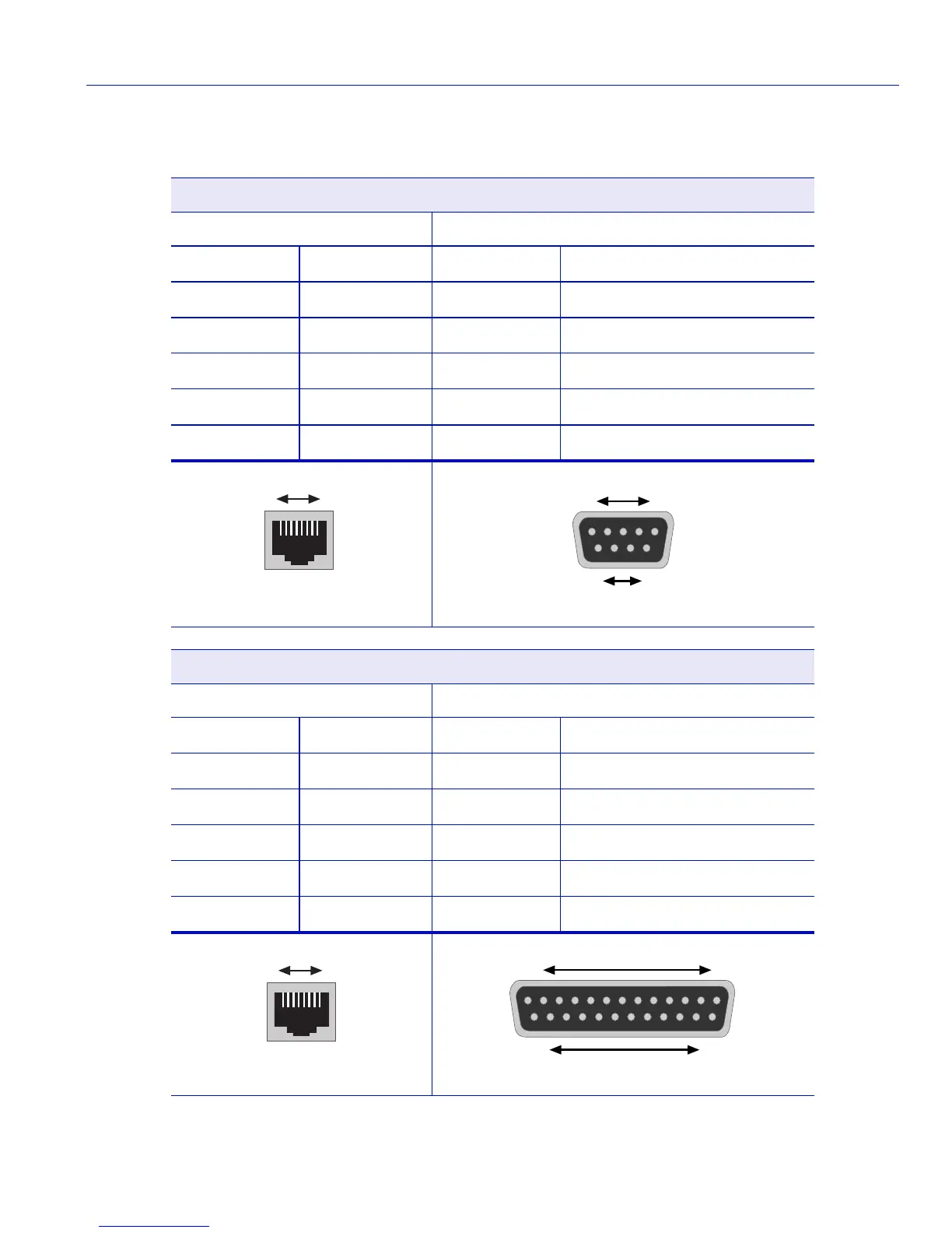
3.10.5 Adapter Wiring and Signal Assignments
Console Port Adapter Wiring and Signal Diagram
RJ45 DB9
Pin Conductor Pin Signal
1 Blue 2 Receive (RX)
4 Red 3 Transmit (TX)
5 Green 5 Ground (GRD)
2 Orange 7 Request to Send (RTS)
6 Yellow 8 Clear to Send (CTS)
VT Series Port Adapter Wiring and Signal Diagram
RJ45 DB25
Pin Conductor Pin Signal
4 Red 2 Transmit (TX)
1 Blue 3 Receive (RX)
6 Yellow 5 Clear to Send (CTS)
5 Green 7 Ground (GRD)
2 Orange 20 Data Terminal Ready
RJ45 Connector (Female)
81
Pins
DB9 Connector (Female)
Pins
15
69
RJ45 Connector (Female)
81
Pins
DB25 Connector (Female)
Pins
113
1425
 Loading...


