Mode Switch Bank Settings B-1
B
Mode Switch Bank Settings
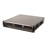
The top cover of the 1G694-13 chassis must be removed to gain access to the mode bank switches.
This appendix covers the following items:
• Required tools (Section B.1)
• Removing the chassis cover (Section B.2)
• Locations, functions, and settings for the mode switches (Section B.3)
B.1 REQUIRED TOOLS
Use the following tools to perform the procedures provided in this appendix:
• Antistatic wrist strap
• Phillips screwdriver
Electrical Hazard: Only qualified service personnel should attempt the following procedures.
Riesgo Electrico: Solamente personal calificado debe intentar este procedimiento.
Elektrischer Gefahrenhinweis: Nur qualifiezierte service personnal die folgende procedure
folgen sollten.

 Loading...


