Installing an Optional Mini-GBIC
3-6 Hardware Installation
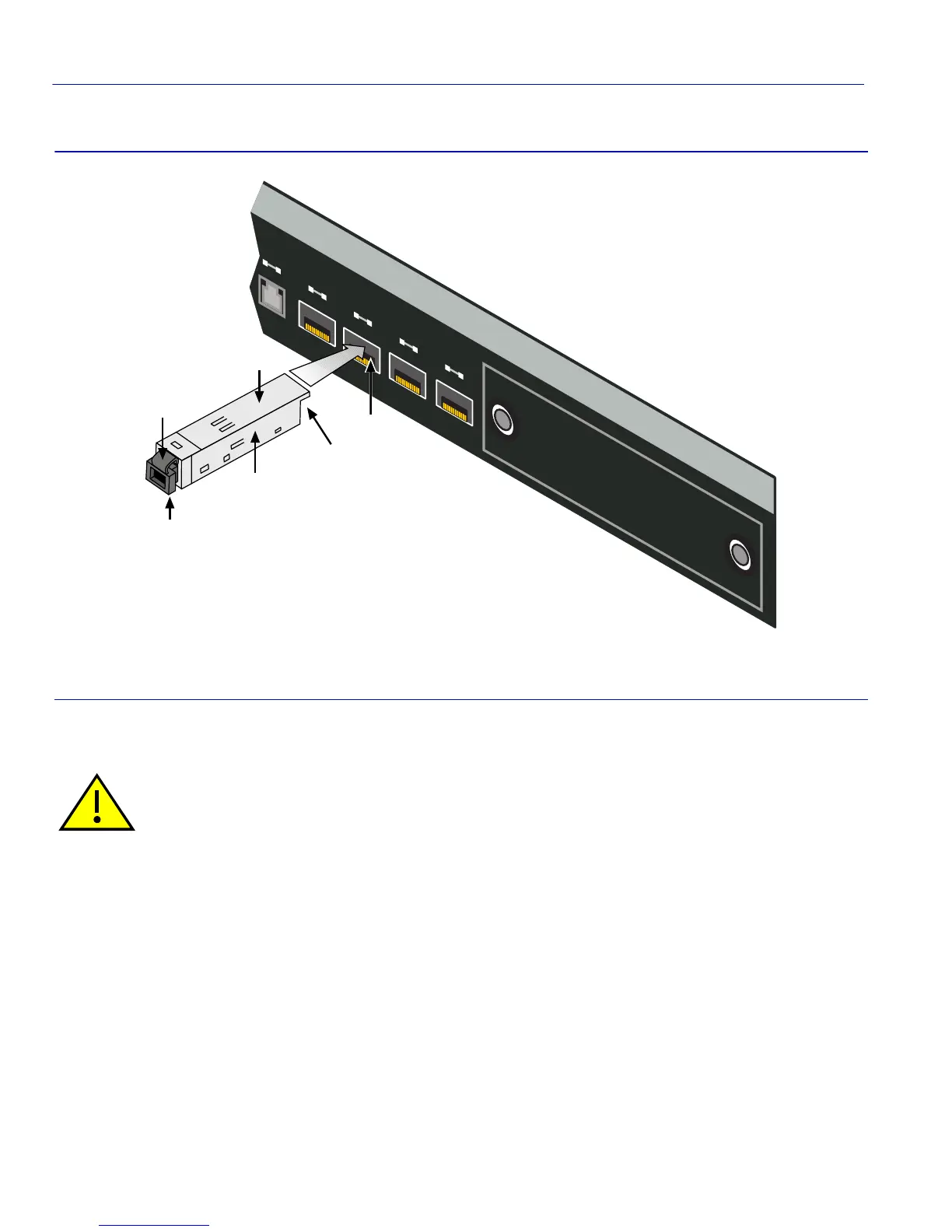
Figure 3-3 Mini-GBIC Installation
Removing a Mini-GBIC
To remove a Mini-GBIC from the switch, refer to Figure 3-3 and proceed as follows:
1. Attach the antistatic wrist strap (refer to the instructions in the antistatic wrist strap package)
before removing the Mini-GBIC.
2. Remove the network cable connected to the Mini-GBIC.
➀
Mini-GBIC
➃
Switch port slot
➁
Mini-GBIC, top side
➄
Mini-GBIC, protective dust cover
➂
7-Pin edge connector (insertion side)
➅
Locking tab
Caution: Do NOT remove a Mini-GBIC from a slot without releasing the locking tab located under
the front bottom end of the Mini-GBIC
. This can damage the Mini-GBIC.
The Mini-GBIC and switch are sensitive to static discharges. Use an antistatic wrist strap and
observe all static precautions during this procedure. Failure to do so can result in damage to the
Mini-GBIC and switch. Always leave the Mini-GBIC in the antistatic bag or an equivalent antistatic
container when not installed.
8
9101112
Ã
Â
Å
À
Á
Ä