Connecting to the Network
Hardware Installation 3-17
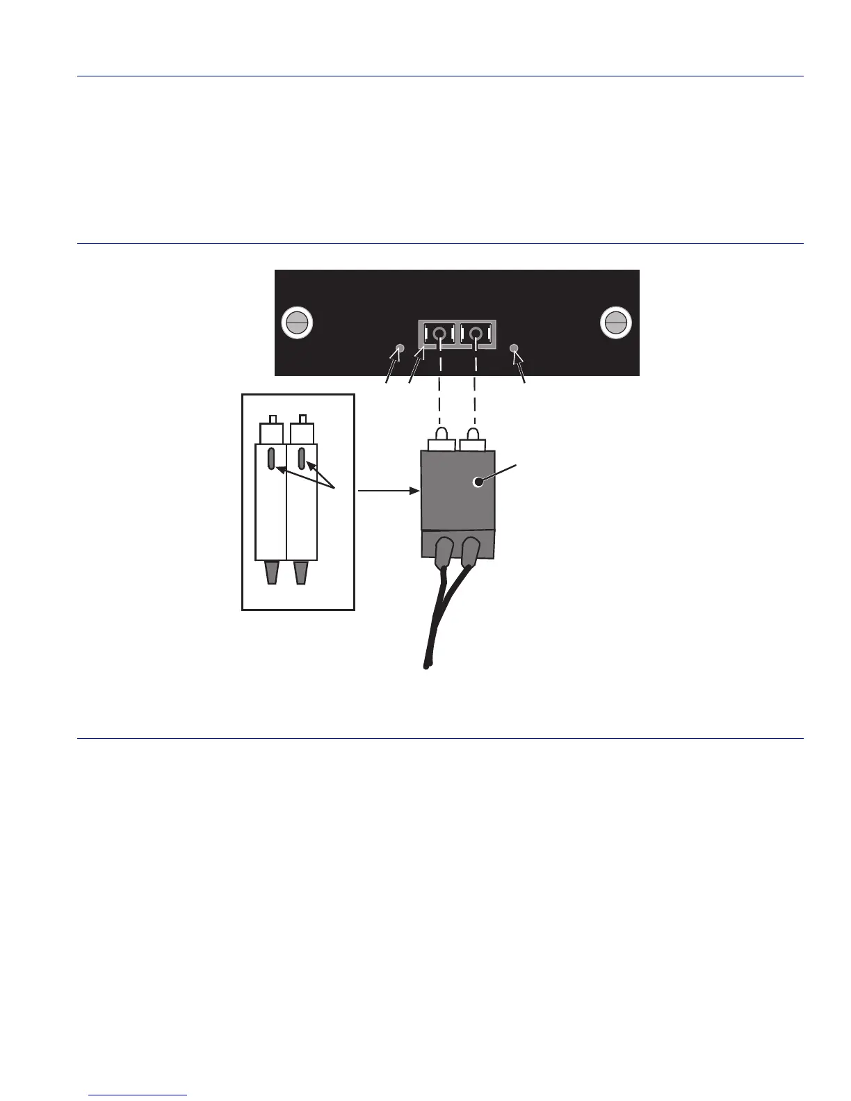
2. Refer to Figure 3-10 and insert one end of the SC cable connector ➀, key side down ➁, into the
SC port interface connector
➂. Ensure that the appropriate cable is used for the application of
the SC port connection. Refer to Appendix A for the appropriate fiber optic cable to be used in
the installation.
Figure 3-10 SC Fiber Optic Cable Connection
3. At the other end of the fiber optic cable, attach the SC connector to the other device.
4. Verify that a link exists by checking that the port RX LED
➃ is on (flashing amber, blinking
green, or solid green). If the RX LED is off, there is no link. Perform the following steps until it
is on:
a. Check that the device at the other end of the link has power turned on and is compatible.
b. Verify proper crossover of fiber strands between the port on the switch and the fiber optic
device at the other end of the fiber optic link segment.
➀
SC cable connector
➃
Link LED (RX)
➁
Latch keys (bottom of SC connector)
➄
Activity LED (TX)
➂
SC port Interface connector
ZPIM1-01
RX TX
À
Á
Ã
Â
Ä
 Loading...


