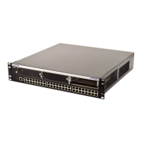
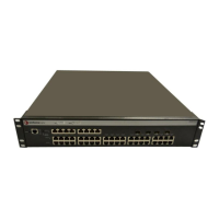
Unpacking the Switch
3-2 Hardware Installation
3.2 UNPACKING THE SWITCH
Unpack the switch as follows:
1. Open the box and remove the packing material protecting the switch.
2. Verify the contents of the carton as listed in Table 3-1.
3. Remove the tape seal on the non-conductive bag to remove the switch.
4. Perform a visual inspection of the device for any signs of physical damage. Contact
Enterasys Networks if there are any signs of damage. Refer to Section 1.6 for details.
3.3 INSTALLING OPTIONS
The 1G694-13 has one expansion slot for an optional 10-Gigabit Ethernet expansion module and
four expansion port slots for optional Mini-GBICs. For instructions to install an Ethernet
expansion module, proceed to Section 3.4. To install a Mini-GBIC, proceed to Section 3.5.
Table 3-1 Contents of Shipping Carton
Item Quantity
1G694-13 1
Antistatic Wrist Strap 1
DB9 to RJ45 Adapter 1
Rackmount Kit 1
Manual Accessory Kit 1
Power Cord 2
Note: If you are installing the 1G694-13 in a rack, it is recommended that you install an optional
Ethernet expansion module or Mini-GBIC in the 1G694-13 first.
Caution: The expansion module is NOT hot-swappable. The switch must be powered down
before the expansion module is installed or removed. Hot-swapping the expansion module while
the switch is powered on could cause the device to stop forwarding frames.

 Loading...


