Installing an Optional Ethernet Expansion Module
3-4 Hardware Installation
3.4.2 Installing an Ethernet Expansion Module
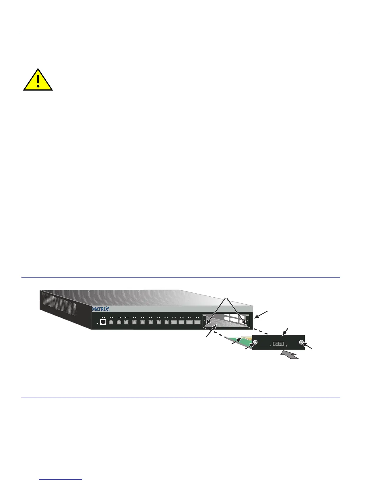
Refer to Figure 3-2 and proceed as follows:
1. After completing the removal of the coverplate
, align the Ethernet expansion module ➀ with the
guides
➁ inside the option slot ➂ in the 1G694-13 front panel ➃. Then slide the Ethernet
expansion module
➀ into the slot until its rear connector ➄ is fully engaged.
2. Tighten the two captive screws
➅ on the Ethernet expansion module ➀ to secure it to the
1G694-13 front panel
➃.
This completes the Ethernet expansion module installation. If you are installing options, proceed
as follows:
• To install a Mini-GBIC, proceed to Section 3.5.
• To install a XENPAK module (10GBASE-LR) in a ZPIM1-06 expansion module, proceed to
Section 3.6.
Otherwise, proceed to Section 3.7 to install the 1G694-13 on a shelf or tabletop, or Section 3.8 to
install the 1G694-13 into a standard 19-inch rack.
Figure 3-2 Installing the Ethernet Expansion Module
Caution: Expansion modules are NOT hot-swappable. The switch must be powered down before
an expansion module (ZPIM1-01 or ZPIM1-06) is installed or removed. Hot-swapping the
expansion module while the switch is powered on could cause the device to stop forwarding
frames.
➀
Ethernet expansion module
➃
1G694-13 front panel
➁
Guides
➄
Rear connectors
➂
Option slot
➅
Captive screws
1G694-13
2
3
4
5
6
7
8
9
10
1
1
12
Reset
Console
CPUPWR
1
Ã
Á
Â
ZPIM1-01
RX TX
Å
Ä
Å
À
 Loading...


